WORKSHOP MANUAL
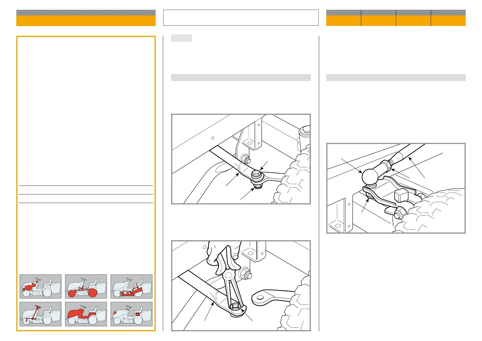
Map of functional units
MP 84/98 - MP 84/98 Hy
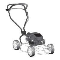
To replace, unscrew the nut (2) with the screw (3) and
remove the bushing (4) using pliers.
Click the new bush (4) and tighten the nut (2) to the
prescribed value.
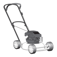
B) Adjustment of the steering wheel
Check that the toe-in is correct (point «A») and align
the front wheels.
If the steering wheel is not straight, dismantle the ar-
ticulated joint (5) and screw down or up on the tie-rod
(6) for the necessary amount.
On assembly, fully tighten the locknut (7) and the fa-
ste ning nut (8).
NOTE Before any other action, check that the joint
fastenings have not worked loose.
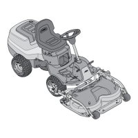
A) Toe-in check
The gap between the connection rod holes (1) on the
wheels ensures correct front wheel toe-in check with-
out requiring adjustment.
Toe-in check may only change due to rod deformation
(1) or due to spindle bushing wear.
General informations
The correct steering geometry is given by the va
lues of the centre distance between the joints of
the tension rod and the wheel connecting rod.
Any faults caused by knocks or accidents result
in re duced driving precision and increased wear
on the tyres. These can be overcome as follows:
– uneven or excessive wear on the front tyres =
incorrect toein
– the machine does not maintain a straight line
when the steering wheel is straight = adjust
ment of tierods.
Related topics
---
Tightening torques
2 Connection rod fastening nuts ....... 25 ÷ 30 Nm
8 Nut for articulated joint ................... 45 ÷ 50 Nm
STEERING GEOMETRY ADJUSTMENT
CHAPTER REVISION FROM ... PAGE
4.7 0 2018 1 of 1
41
1
2
3
6
5
8
7