Hardware layout and configuration UM1855
28/100 DocID027351 Rev 3
2.12 Motor control
The CN2 connector is designed to receive a motor control (MC) module. Table 12 shows the
assignment of CN2 and STM32L476ZGT6 terminals.
Table 12 also lists the modifications to be made on the board versus its by-default
configuration. See Section 2.12.1 for further details.
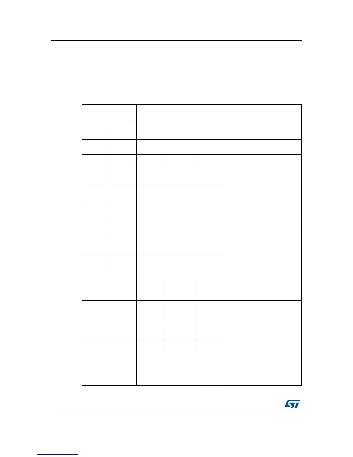
Table 12. Motor control terminal and function assignment
Motor control
connector CN2
STM32L476ZGT6 microcontroller
Terminal
Terminal
name
Port name Function
Alternate
function
Board modifications for
enabling motor control
1
Emergency
Stop
PC9 TIM8_BKIN2 -
Close SB29
Remove MB979 daughterboard
2GND - GND - -
3 PWM_1H PC6 TIM8_CH1 -
Close SB27
Open SB2
Remove MB979 daughterboard
4GND - GND - -
5 PWM_1L PA7 TIM8_CH1N -
Close SB19
Open SB18
Remove R66
6GND - GND - -
7 PWM_2H PC7 TIM8_CH2 -
Close SB30
Open SB4
Remove R33
8GND - GND - -
9 PWM_2L PB0 TIM8_CH2N -
Close SB15
Open SB14
Remove R62
10 GND - GND - -
11 PWM_3H PC8 TIM8_CH3 -
Close SB28
Remove MB979 daughterboard
12 GND - GND - -
13 PWM_3L PB1 TIM8_CH3N -
Close SB13
Open SB12
14 Bus Voltage PC5 ADC12_IN -
Close SB16
Remove MB979 daughterboard
15
PhaseA
current+
PC0 ADC123_IN -
Close SB34
Remove MB979 daughterboard
16
PhaseA
current-
-GND - -
17
PhaseB
current+
PC1 ADC123_IN - Close SB36