DocID027351 Rev 3 17/100
UM1855 Hardware layout and configuration
99
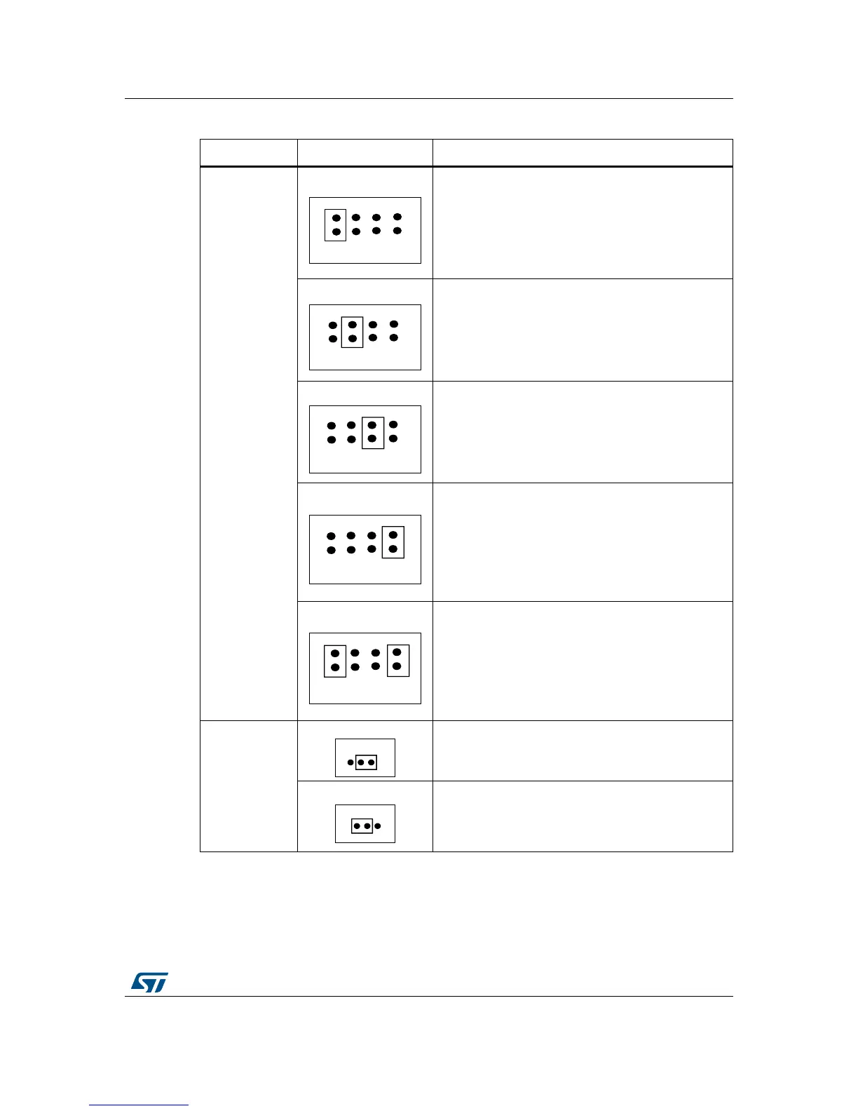
Table 2. Power-supply-related jumper settings
Jumper array Jumper setting Configuration
JP17
Power source
selector
JP17
STM32L476G-EVAL is supplied through CN22 power
jack (marked PSU_E5V). CN6 extension connector
does not pass the 5 V of STM32L476G-EVAL to
daughterboard.
JP17
STM32L476G-EVAL is supplied through CN1 Micro-AB
USB connector. CN6 extension connector does not
pass the 5 V of STM32L476G-EVAL to daughterboard.
JP17
Default setting.
STM32L476G-EVAL is supplied through CN17
Standard-B USB connector. CN6 extension connector
does not pass the 5 V of STM32L476G-EVAL to
daughterboard.
Check JP18 setting in Table 2.
JP17
STM32L476G-EVAL is supplied through pin 28 of CN6
extension connector.
JP17
STM32L476G-EVAL is supplied through CN22 power
jack (marked PSU_E5V). CN6 extension connector
passes the 5 V of STM32L476G-EVAL to
daughterboard. Make sure to disconnect from the
daughterboard any power supply that could generate
conflict with the power supply on CN22 power jack.
JP12
V
bat
connection
JP12
V
bat
is connected to battery.
JP12
Default setting.
V
bat
is connected to V
DD
.