DocID027351 Rev 3 29/100
UM1855 Hardware layout and configuration
99
2.12.1 Board modifications to enable motor control
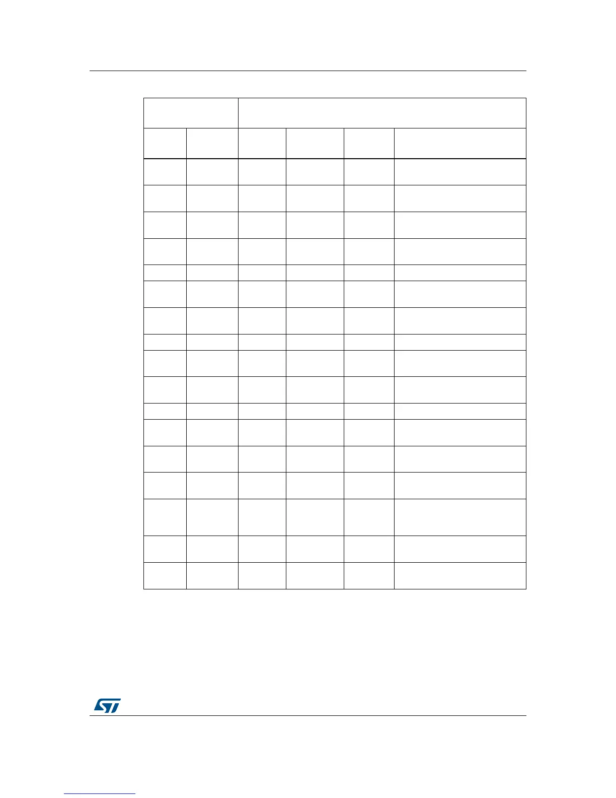
Figure 7 (top side) and Figure 8 (bottom side) illustrate the board modifications listed in
Table 12, required for the operation of motor control. Red color denotes a component to
remove. Green color denotes a component to be fitted.
18
PhaseB
current-
-GND - -
19
PhaseC
current+
PC2 ADC123_IN -
Close SB42
Remove MB979 daughterboard
20
PhaseC
current-
-GND - -
21 ICL Shutout PG6 GPIO -
Close SB5
Remove R35
22 GND - GND - -
23
Dissipative
Brake
PB2 GPIO -
Close SB11
Remove R54
24
PFC ind.
curr.
PC4 ADC12_IN -
Close SB17
Remove MB979 daughterboard
25 +5V - +5V - -
26
Heatsink
Temp.
PA3 ADC12_IN -
Close SB22
Remove MB979 daughterboard
27 PFC Sync PF9 TIM15_CH1 -
Close SB25
Remove R90
28 +3.3V - +3.3V - -
29 PFC PWM PF10 TIM15_CH2 -
Close SB37
Remove R91
30
PFC
Shutdown
PB12 TIM15_BKIN -
Close SB3
Remove MB979 daughterboard
31 Encoder A PA0 TIM2_CH1 ADC12_IN
Close SB35
Remove R83
32 PFC Vac PA6 ADC12_IN -
Close SB20
Open SB21
Remove MB979 daughterboard
33 Encoder B PA1 TIM2_CH2 ADC12_IN
Close SB32
Remove MB979 daughterboard
34
Encoder
Index
PA2 TIM2_CH3 ADC12_IN
Close SB31
Remove MB979 daughterboard
Table 12. Motor control terminal and function assignment (continued)
Motor control
connector CN2
STM32L476ZGT6 microcontroller
Terminal
Terminal
name
Port name Function
Alternate
function
Board modifications for
enabling motor control