Hardware layout and configuration UM1855
58/100 DocID027351 Rev 3
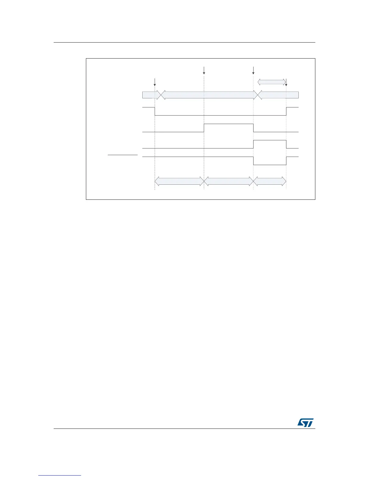
Figure 19. Low power mode IDD measurement timing
2.30.3 IDD measurement in dynamic run mode
In dynamic run mode, the IDD_CNT_EN remains high. The T2 is in conductive state, setting
the shunt resistor to 1 Ω. The U13 path from port 1 to 2 is permanently conductive and the
voltage on the capacitor C73 follows the MCU current consumption. R122 allows filtering
fast changes.
2.30.4 Calibration procedure
For the measurement to be precise, it is mandatory to perform a calibration before the
measurement. The calibration allows subtracting, from the voltage measured across C73,
the offset at the differential amplifier output, described in Section 2.30.1.
The calibration procedure consists in measuring the offset voltage when the current through
the shunt resistor is zero. The current consumption values measured by the microcontroller
are then compensated for offset, by subtracting the now-known offset number from the
measured number. Setting the current through the shunt resistor to zero is reached through
appropriate setting jumpers in the JP11 jumper header.
06Y9
,''B&17B(1
80&8SRUW3%
/2:B32:(5B(1
8FRXQWHUSRUW4
,''B:$.(83
8FRXQWHUSRUW4
,''B:$.(83
8LQYHUWHUWHUPLQDO
WŚĂƐĞϭ WŚĂƐĞϮ WŚĂƐĞϯ
6+VZLWFK8FORVHG
8RSHQ
KLJK,''UDQJH ORZ,''UDQJH KLJK,''UDQJH
,''PHDVXUHPHQWSURFHVVLQSURJUHVV
>ŽǁͲƉŽǁĞƌ
ZƵŶ
ZƵŶ
0&8RSHUDWLQJPRGH
6WDUW
SURFHVV
6WDUWORZSRZHU,''
VDPSOLQJ
+ROGORZSRZHU,''VDPSOH
:DNH0&8XS
(QG
SURFHVV
$FWLRQE\0&8
$FWLRQE\ORJLF
ŵĞĂƐƵƌĞŵĞŶƚ
aPV aPV