Hardware layout and configuration UM1855
56/100 DocID027351 Rev 3
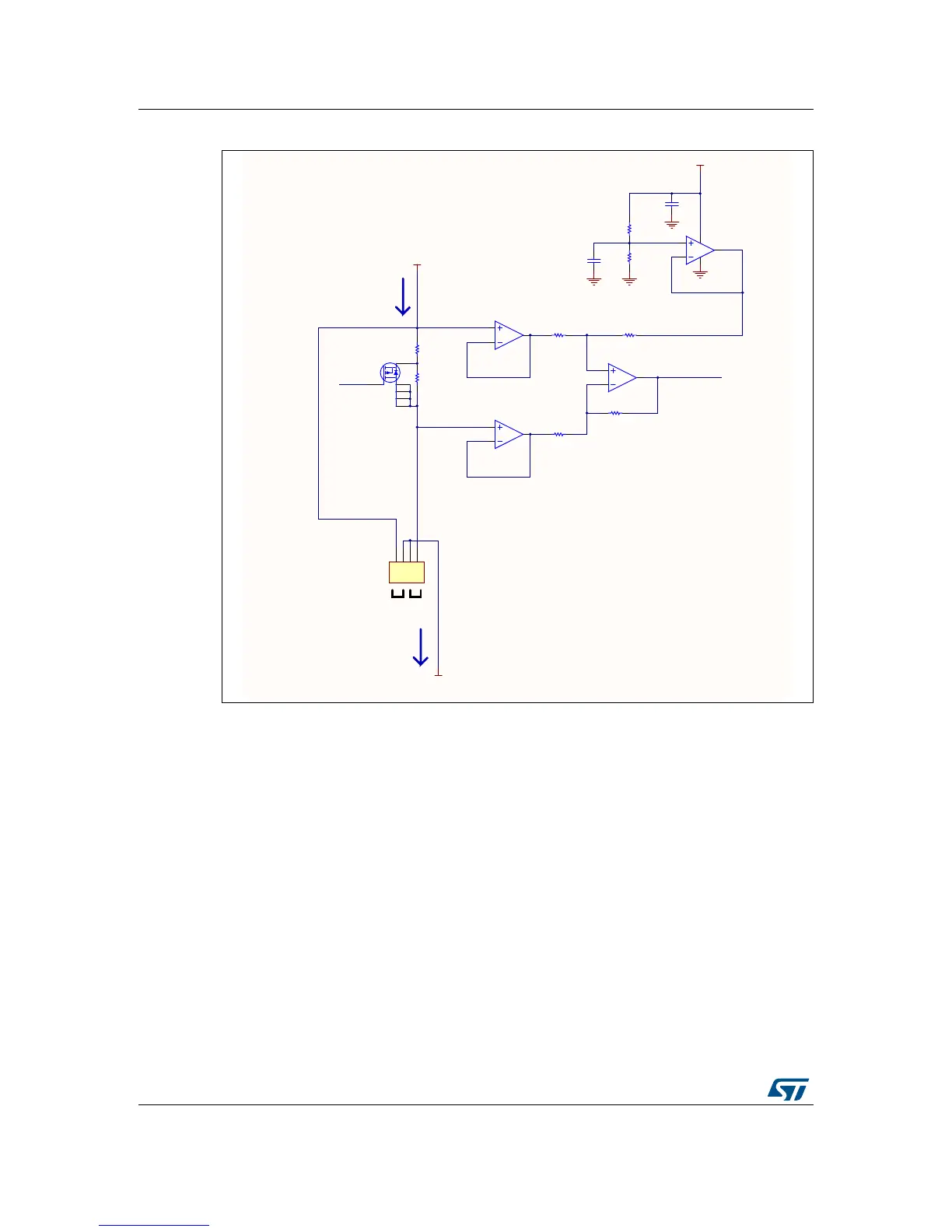
Figure 17. Schematic diagram of the analog part of IDD measurement
2.30.2 Low-power-mode IDD measurement principle - logic part
The target microcontroller can only carry out actions for measuring a voltage when in
dynamic run mode. This is the reason why, voltage representing the current consumed by
the microcontroller when in low-power mode needs to be held by a sample-and-hold circuit,
for being exploited by the microcontroller at a later time, when back in dynamic run mode.
The sample-and-hold (S&H) circuit is built with U13 switch, R122 resistor and C73 sampling
capacitor.
The measurement of low-power-mode current consumption is started and end by the
microcontroller in its dynamic run mode. As, between the start and end event, the
microcontroller must transit through one of its low-power modes, an extra logic is required to
time and control events during this state. It consists of U14 counter, U16 inverter and the
transistor T3. Figure 18 shows the corresponding schematic diagram.