DocID027351 Rev 3 39/100
UM1855 Hardware layout and configuration
99
2.16 TFT LCD panel
STM32L476G-EVAL is delivered with MB989P, a daughterboard plugged into the CN19
extension connector. It bears a TFT 2.8-inch color LCD panel with resistive touchscreen and
an on-board controller. Section 2.18 provides further information.
Thanks to level shifters on all signal lines, the TFT LCD panel can operate with the entire
operating voltage range of STM32L476G-EVAL.
The TFT LCD panel is attached to the 16-bit data bus and accessed with FMC. The base
address is 0x6800 0000, corresponding to NOR/SRAM3 bank1. The panel is selected with
LCD_NE3 chip select signal generated by PG10 port of the STM32L476ZGT6. Address
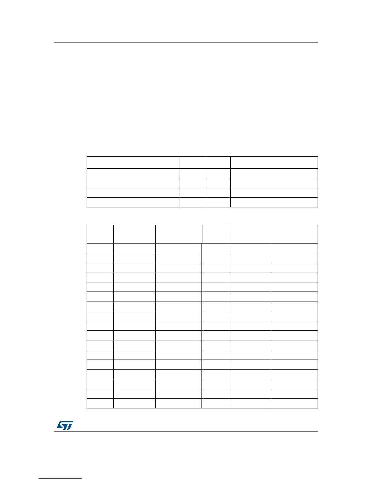
lines A0 and A1 determine the panel resources addressed, as depicted in Table 19.
Table 20 gives the CN19 extension connector terminal assignment.
Table 19. Access to TFT LCD resources with FMC address lines A0 and A1
Address A1 A0 Usage
0x6800_0000 0 0 Read register
0x6800_0002 0 1 Read Graphic RAM (GRAM)
0x6800_0004 1 0 Write register
0x6800_0006 1 1 Write graphic RAM (GRAM)
Table 20. Assignment of CN19 connector terminals of TFT LCD panel
CN19
terminal
Terminal
name
MCU
port
CN19
terminal
Terminal
name
MCU
port
1CSN PG10 2 RS PF0
3 WRN PD5 4 RDN PD4
5 RSTN RESET# 6 D0 PD14
7 D1 PD15 8 D2 PD0
9 D3 PD1 10 D4 PE7
11 D5 PE8 12 D6 PE9
13 D7 PE10 14 D8 PE11
15 D9 PE12 16 D10 PE13
17 D11 PE14 18 D12 PE15
19 D13 PD8 20 D14 PD9
21 D15 PD10 22 BL_GND -
23 BL_CONTROL - 24 +3V3 -
25 +3V3 - 26 26 -
27 GND - 28 BL_VDD -
29 SDO - 30 SDI -
31 XL I/O expander_X- 32 XR I/O expander_X+
33 YD I/O expander_Y- 34 YU I/O expander_Y+