111 B58FZS 0000000078 EN 002
CONTENTS
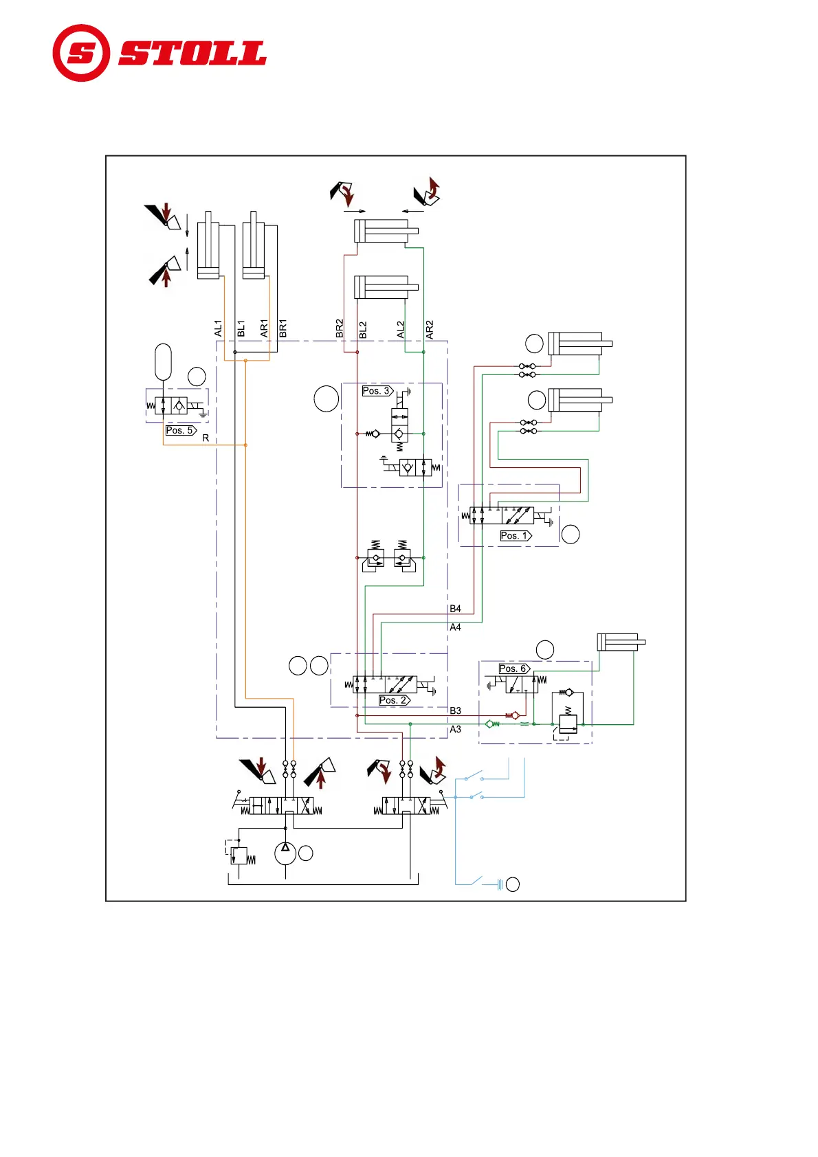
11.4 Hydraulic diagram
11.4.1 Hydraulic diagram FS and FS-rapid emptying
Fig. 102 Hydraulic diagram FS and FS-rapid emptying
Legend
F1, S1 4th control circuit (optional)
F2, S2 3rd control circuit (optional)
F3b, S3b Rapid emptying (only FS-rapid emptying)
F5, S5 Comfort-Drive (optional)
F6, S6 Hydro-Lock (optional)
P Tractor pressure
Z Ignition
B04G
210 bar 210 bar
P
Z
S1
S2 / S3b
A1 B1 A2B2
A2 A1
C2 C1
B2
B1
F2
F1
F1
F1
F2
F5
F3b
F6
150 bar