45 B58FZS 0000000078 EN 002
FUNCTIONS
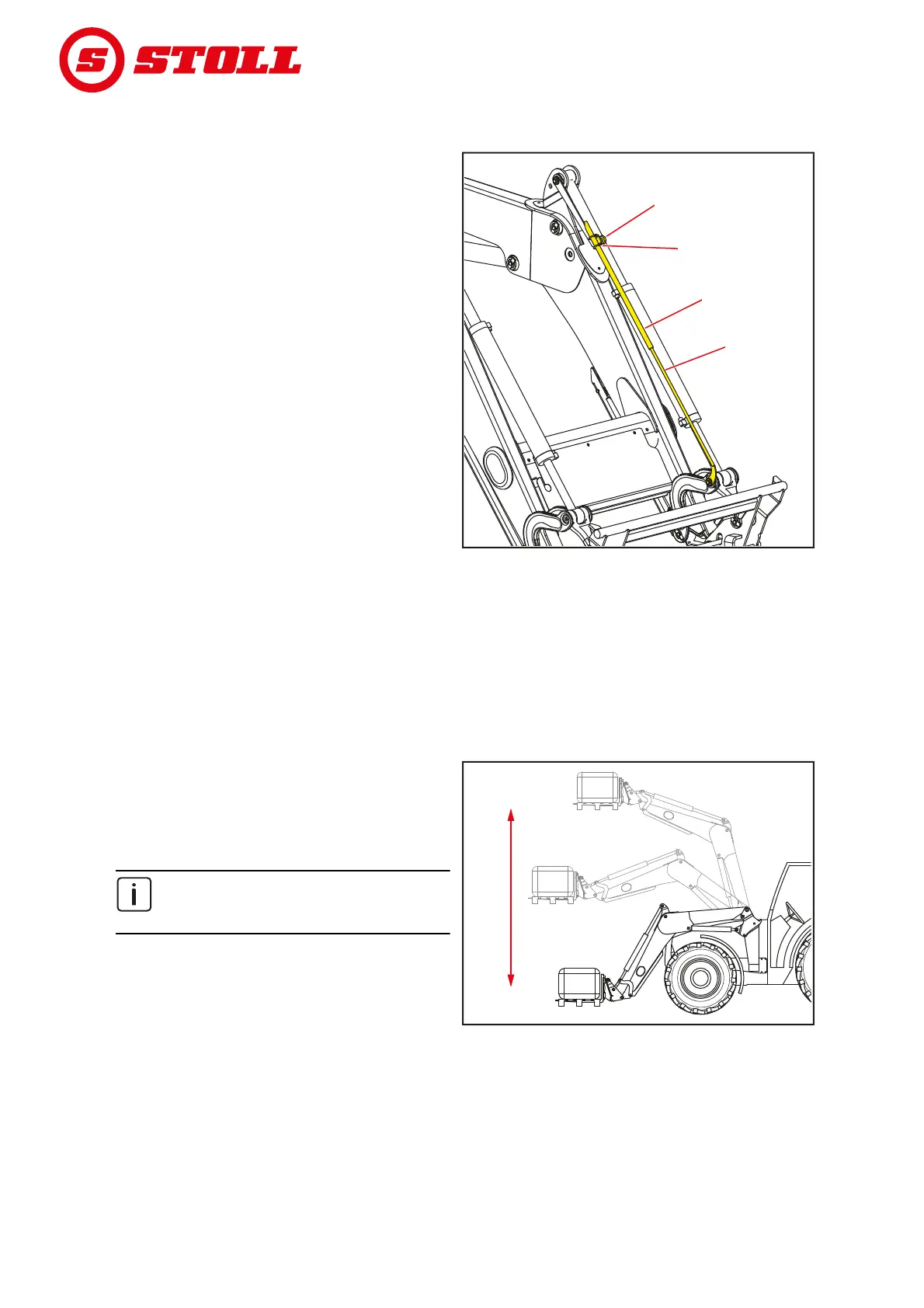
4.4 Indicator for implement position
The indicator for the implement position is
located on the left implement cylinder. It allows
the horizontal position of the implement to be
read from the driver's seat.
The rod is attached on the lower bearing pin and
runs through the tube, which is attached to the
upper bearing pin with the support. When
dumping or scooping, the rod moves in the tube.
When the implement is in horizontal position, the
rod and the tube are flush.
Setting of the indicator:
(1) Position the implement horizontally.
(2) Lower the front loader to the ground.
(3) Switch off the tractor.
Apply the parking brake.
Stop the engine.
(4) Loosen the clamping screw.
(5) Push the tube into the support until the top
end of the tube is flush with the rod.
(6) Tighten the clamping screw.
The indicator is set.
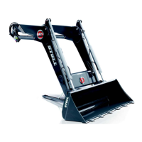
4.5 Parallel motion (FZ, FZ-L)
With the parallel motion, the guide linkage
ensures constant orientation/inclination of the
implement.
The function is particularly suitable for loading
pallets and stacking bales.
The function can only be executed when
the implement is horizontal or in scooping
position.
Fig. 28 Indicator for implement position
Legend
1 Clamping screw
2 Holder
3Tube
4Rod
11
3
3
4
4
2
2
B01E
Fig. 29 Parallel motion
B06G