B58FZS 0000000078 EN 002 114
TECHNICAL SPECIFICATIONS
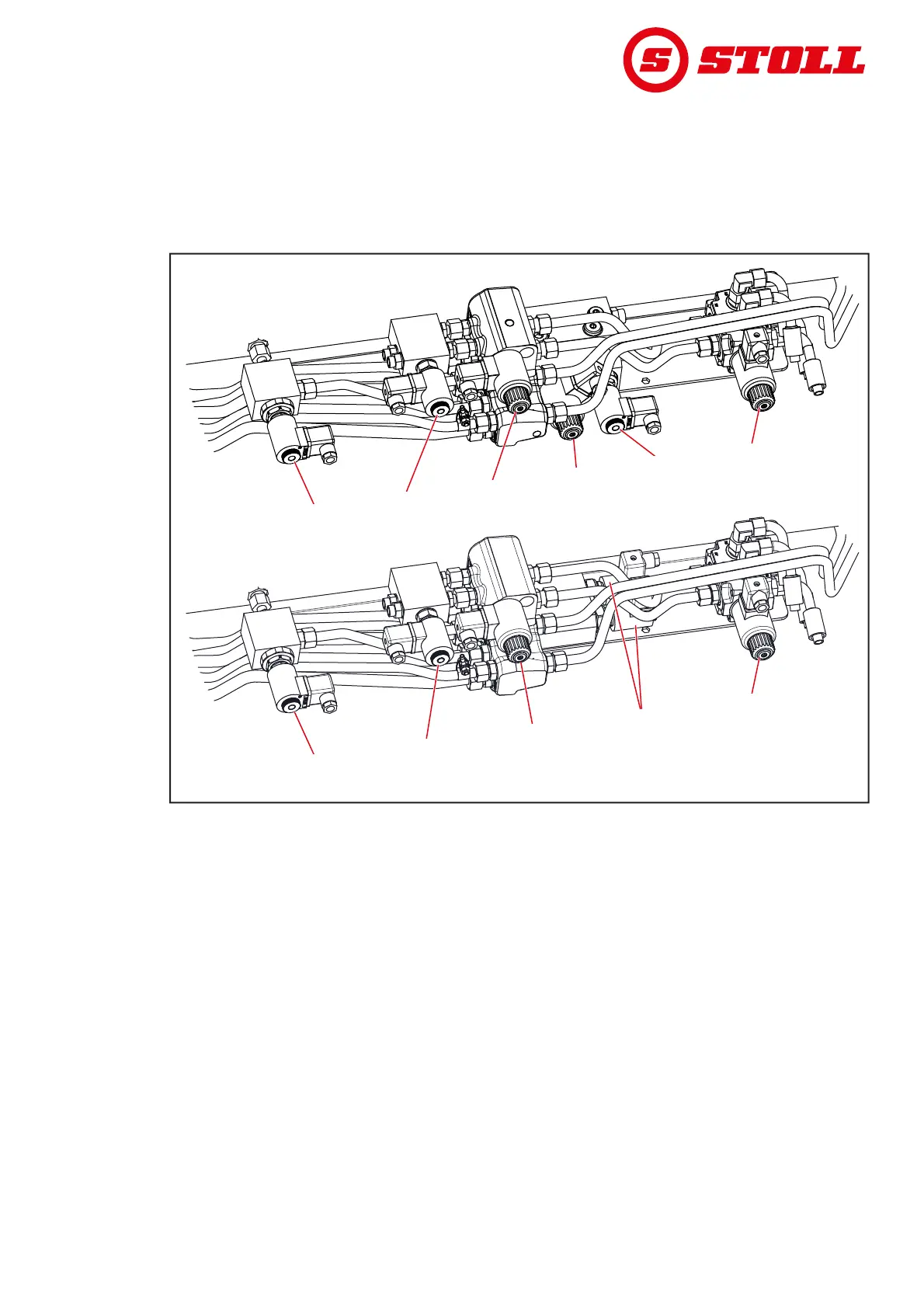
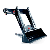
11.6 Arrangement of the hydraulic valves for additional functions
The figure shows the arrangement of the hydraulic valves for the additional functions Q1 to Q6 on the
cross bar of the front loader lifting arm. The maximum equipment for the FZ front loader (including FZ-L)
and FS (including FS-rapid emptying) is shown.
The designations Q1 to Q6 correspond to the designations in the electric circuit diagram
(see 11.5 Electric circuit diagram).
Fig. 105 Arrangement of the hydraulic valves for additional functions
Legend
Q1 Hydraulic valve for 4th control circuit
Q2 Hydraulic valve for 3rd control circuit
Q3 Hydraulic valve for rapid emptying (on FS-rapid emptying) or quick emptying (on FZ-L)
Q4 Hydraulic valve for re-scooping or return-to-level (on FZ-L)
Q5 Hydraulic valve for electrically controlled Comfort Drive
Q6 Hydraulic valve for Hydro-Lock (hydraulic implement locking mechanism)
Q1Q1
Q6
Q6
Q5
Q5
Q4
Q4
Q2
Q2
Q3
Q3
Q1Q1
Q6
Q6
Q5
Q5
Q2
Q2
Q3
Q3
FZ
FS
B07V