6
General
Welcome
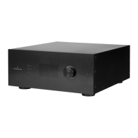
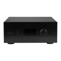
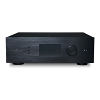
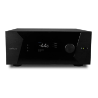
Thank you for your purchase of a StormAudio
ISP Immersive Sound Processor. The ISP has
been designed to provide state of the art audio
performance with immersive surround formats and
legacy surround formats alike. Innovative hardware
and soware make it possible to customize theaters
of up to 32 channels. Its modular nature allows for
matching any inputs / outputs requirements as
well as an upgrade capability for many years to
come.
Included In The Box
• This Owner’s Manual / Installer Guide
• Power cable for your locality
• Rack mount ears (requires T20 Torx screwdriver
to mount)
• UMIK-1 USB microphone and extension for RTA
and StormMonitoring feature.
Features
StormAudio ISP includes the following features:
• 7 Input / 2 Output HDMI switch, 3 TOSLINK and
3 RCA S/PDIF legacy digital inputs plus soware
congurable analog input (7.1 or 4x Stereo)
• Mandatory network connectivity for control
and rmware updates.
• Up to 32 soware congurable outputs (analog
or digital) + Downmix L/R XLR pair
• Up to 16 congurable digital inputs
• 4 programmable trigger outputs
• IR control
• Available control modules for 3rd party
automation systems available on the Client
Portal at http://www.stormaudio.com
Shipping Box and Packing Material
Please keep the original shipping box and all
packing material. In the unlikely event you have a
problem and must return it for service, you must
use the proper packing material as the unit is
not insurable by carriers otherwise. Replacement
packing materials is available from StormAudio for
a small fee.
Installation
Prepare your installation site by following the steps
below: Consult page “Rear Panel” on page 4
for rear panel diagram indicating location of key
connections.
1. For non North American models that are
delivered with a fuse attached to the AC cord,
install the fuse before plugging the unit into
mains power.
2. Ensure your electrical circuit has a good
ground connection with all audio equipment
connected to the same ground node to avoid
noise or hum due to a ground loop.
3. Prepare attached equipment such as display or
projector, audio ampliers, speakers, network
switch and associated cables.
4. Network should be running a DHCP server to
enable the ISP to obtain an IP address.
Ventilation
The ISP is a cool-running line level component. It
generates far less heat than ampliers and many
other components. It can be safely placed inside
furniture or an equipment rack. However, it should
not be tightly enclosed. Some airow is desired.
Note that the rear panel fan needs to be able to
circulate air especially when the ISP is under heavy
load.
Connecting to A/C Power
If necessary, install the included fuse into the fuse
socket. Plug the IEC-320 C14 end of the power
cord into the ISP, then plug the other end into an
approved and grounded A/C receptacle.
Connecting to Network
Using at CAT5e or better cable, connect the ISP to
your local area network. See “Get Network Access”
on page 7 to identify IP address.
Connect IR Interface (Optional)
Should you choose to use an IR interface, you will
need to connect an IR receiver to the IR Input of the
ISP.
Connect Source Components
Legacy digital sources can be connected to the