Status LEDs and System Buttons
Troubleshooting the Hardware
3-7
system components are running normally and all
paired components have fully operational partners.
2. The four Memory Faults LEDs described briefly in
Ta bl e 3- 2 are described in detail in Table 5-1.
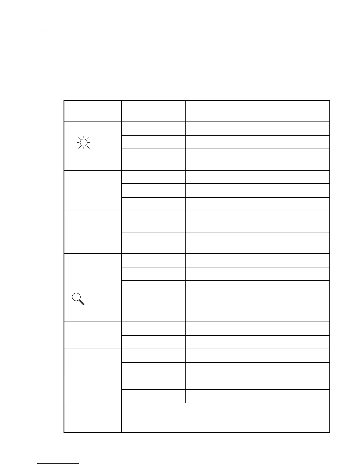
Table 3-2. CPU-I/O Enclosure LEDs
LED Label or
Icon State Description
Power Off AC power off (cord is removed).
Green On DC power on.
Blinking Green AC power on and DC power off. System is on
standby power only.
SAFE TO PULL Off CPU-I/O enclosure offline.
Green On CPU-I/O enclosure safe to pull.
Blinking Green CPU-I/O enclosure not safe to pull.
PRIMARY Off The I/O element in this CPU-I/O enclosure is not
the active element.
Green On The I/O element in this CPU-I/O enclosure is the
active element.
System ID
†
One
on front and one
on back of
system
Off No request to identify system activated.
Green On Identify system activated by ID button.
Blinking Green Remote request from the ftSMC snapin (on
Windows systems) or the
ftsmaint identify [start|stop] path
(on Linux systems).
I/O
†
Off Normal operation.
Yellow On Fault detected.
CPU
†
Off Normal operation.
Green On Fault detected.
FAN
†
Off Normal operation.
Yellow On Fan fault.
MSB ... LSB MSB and LSB: most-significant bit and least-significant bit.
These four memory fault LEDs, bracketed by the DIMM Number label,
are explained in “Memory Fault LEDs” on page 3-8 and
Table 5-1.