0702-002-700 Rev-J EN
www.stryker.com 7
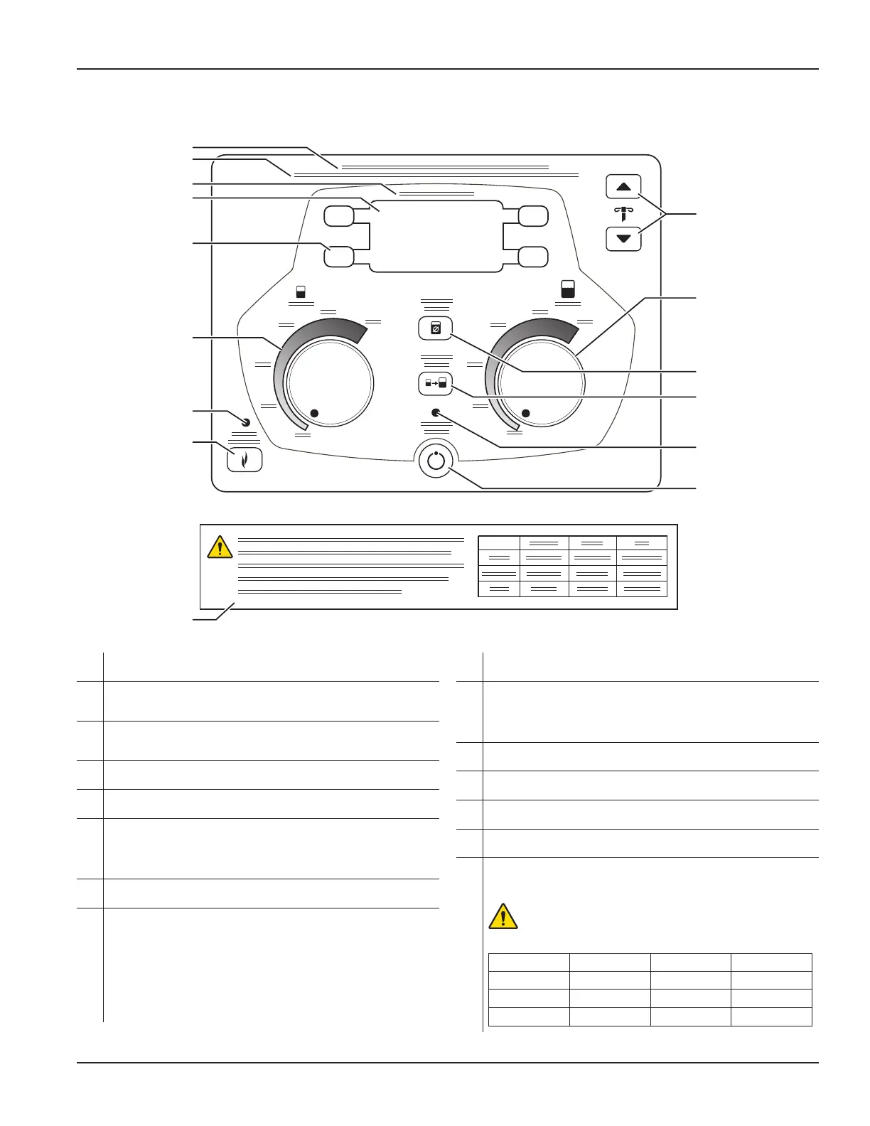
Control Panel (see figure 2)
Features (cont’d)
A
Max. Vacuum Limit: 21 in-Hg, 530 mm-Hg, 71 kPa - See User/Patient
Safety for WARNING information.
B
The suction levels of each canister are interdependent and linked to a
common vacuum source - See User/Patient Safety section for WARNING
information.
C
High Vacuum / High Flow - Indicates this equipment is a high vacuum,
high flow medical device. See User/Patient Safety section for WARNING
information.
D
Control Panel Display - Provides vacuum level values for each canister,
system status and error messages; also displays wash cycle options.
E
Control Panel Display Push Buttons (four) - Press the appropriate button
when the display provides push button label areas.
F
4-liter Vacuum Limit Setting Dial - Turn the dial to adjust the vacuum limit
level (fluid suction) of the 4-liter canister. Graduations of 20% are provided
as an adjustment guide. The vacuum level status will be indicated on the
control panel display as a limit SET value or real time ACTUAL value. See
Control Panel Display.
G
Smoke Evacuator Indicator - Illuminates when the smoke evacuation
capability is activated.
H
Smoke Evacuator Button - The smoke evacuator removes surgical smoke
from a surgical site during cautery or laser surgery. The smoke evacuator
has three distinct modes: manual, automatic, and off. Press the button
once to access the manual mode of operation. In manual mode, the smoke
evacuator will operate at the specified power setting whether smoke is
present or not. Press the button a second time to access the automatic
mode of operation. In automatic mode, the smoke evacuator will operate at
the specified power setting if smoke is present. If smoke is not detected,
the smoke evacuator will operate at a 20% power setting automatically.
Press the button a third time to stop the smoke evacuator.
I
IV Pole Height Adjust Buttons - Press the UP or DOWN arrow button to
increase or decrease the height of the IV pole, respectively.
J
20-liter Vacuum Limit Setting Dial - Turn the dial to adjust the vacuum limit
level (fluid suction) of the 20-liter canister. Graduations of 20% are provided
as an adjustment guide. The vacuum level status will be indicated on the
control panel display as a limit SET value or real time ACTUAL value. See
Control Panel Display.
K
Volume Reset Button - Press the button to reset the displayed fluid volume
of both canisters to zero values.
L
Empty Tank Button - Press the button to empty the contents of the small
canister into the large canister.
M
Stand-by (Vacuum System) Indicator- Illuminates when the system’s fluid
suction capability is activated.
N
Stand-by (Vacuum System) Button- Press the button to activate or
deactivate the system’s fluid suction capability.
O
Warning Label and Vacuum Range Adjustment Table - Read the WARNING
and reference the appropriate vacuum values when adjusting the Vacuum
Limit Setting Dials. The label and table are located below the control panel.
WARNING: HighVacuum/HighFlow[530mm-Hg,21inchHg,
71kPa]–DONOTapplyhighflowsuctioninapplicationsthat
may result in severe injury or death, for example, passive chest
drainage.
mm-Hg in-Hg kPa
HIGH
120 – 530 4.8 – 21.0 16.0 – 71.0
MEDIUM
80 – 115 3.2 – 4.6 11.0 – 15.0
LOW
50 – 75 2.0 – 3.0 7.0 – 10.0
A
B
C
D
E
F
G
H
I
J
K
L
M
O
N
Figure 2 Control Panel

 Loading...


