Troubleshooting Guides
Integrated
(700-
3
BASE)
Series
8-18
#3758424 - Revision B - December, 2005
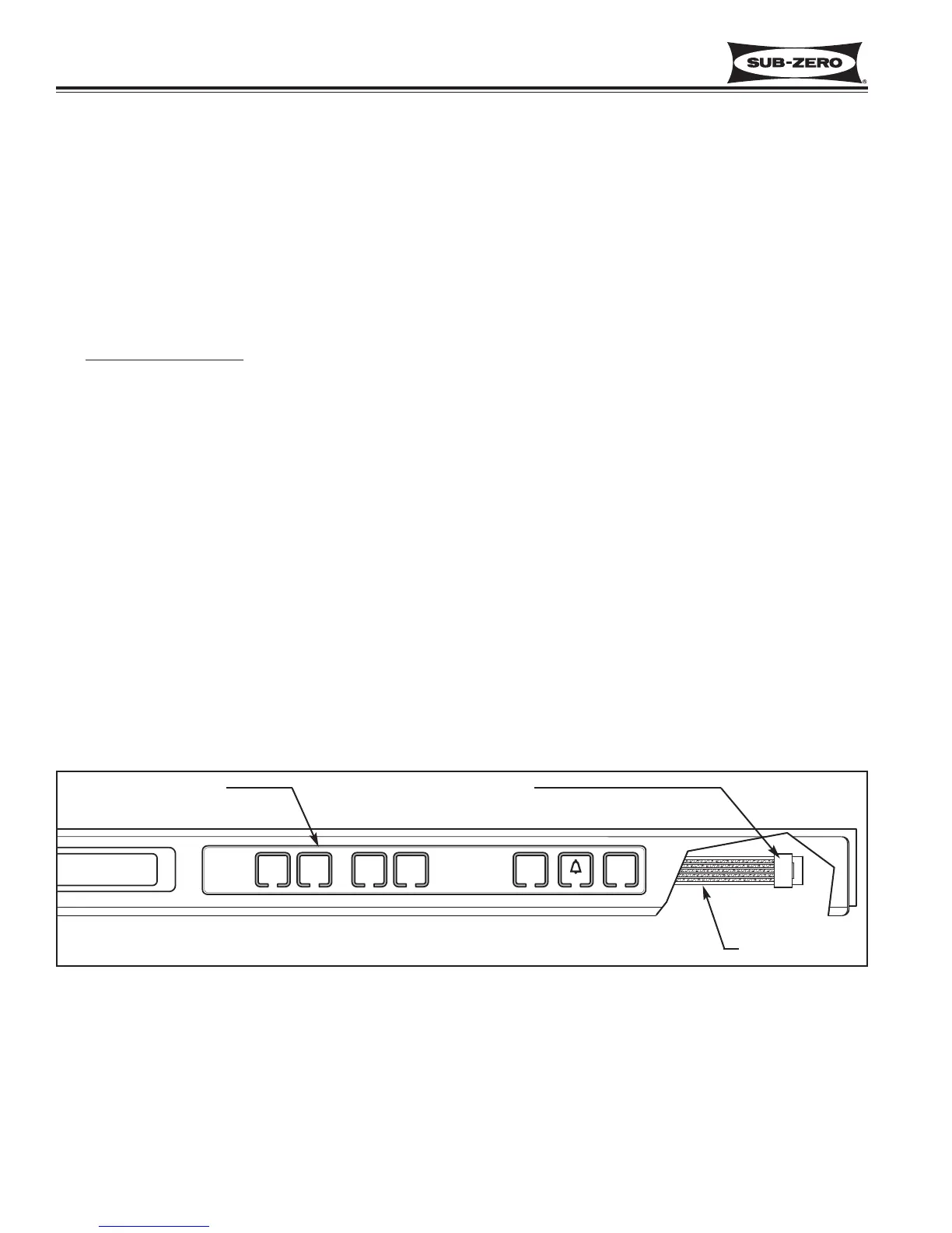
BASE UNIT MEMBRANE SWITCH / RIBBON CABLE TEST
If the integrity of a Base Unit control panel assembly is suspect, continuity tests should be performed at the mem-
brane switch ribbon cable terminal housing. Begin by removing the control panel assembly from the unit and place it
on a solid surface. Disconnect the ribbon cable from control panel PC board.
How To Identify Pin 1 on Terminal Housing
The ribbon cable wires are exposed at the back of the terminal housing, but since there are two vendors of the
membrane switch, determining the location of pin 1 is not always easy. To identify the pins, follow these guidelines:
1. If terminal housing is BLUE, then pin 1 is closest to arrow on housing.
2. If terminal housing is BLACK, check for continuity between first two pins at each end of housing while pushing
Freezer W
ARMER key
. If there is continuity, then pin 1 is at that end.
700BCI-3 Membrane Switch/Ribbon Cable Test Procedure
1. Press no keys on membrane switch. Check for continuity between all pin combinations. With no keys pressed,
there should be no continuity between any pins.
2. Press UNIT ON/OFF key, there should be continuity across pins 3 & 4.
3. Press Door Ajar Alarm ON/OFF key, there should be continuity across pins 2 & 4.
4. Press Freezer WARMER key, there should be continuity across pins 1 & 2.
5. Press Freezer COLDER key, there should be continuity across pins 1 & 5.
6. Press Refrigerator WARMER key, there should be continuity across pins 4 & 5.
7. Press Refrigerator COLDER key, there should be continuity across pins 1 & 3.
NOTE: If any of the tests show failure, replace entire control panel assembly.