Electronic Control System
Integrated
(700-
3
BASE)
Series
3-20
#3758424 - Revision B - December, 2005
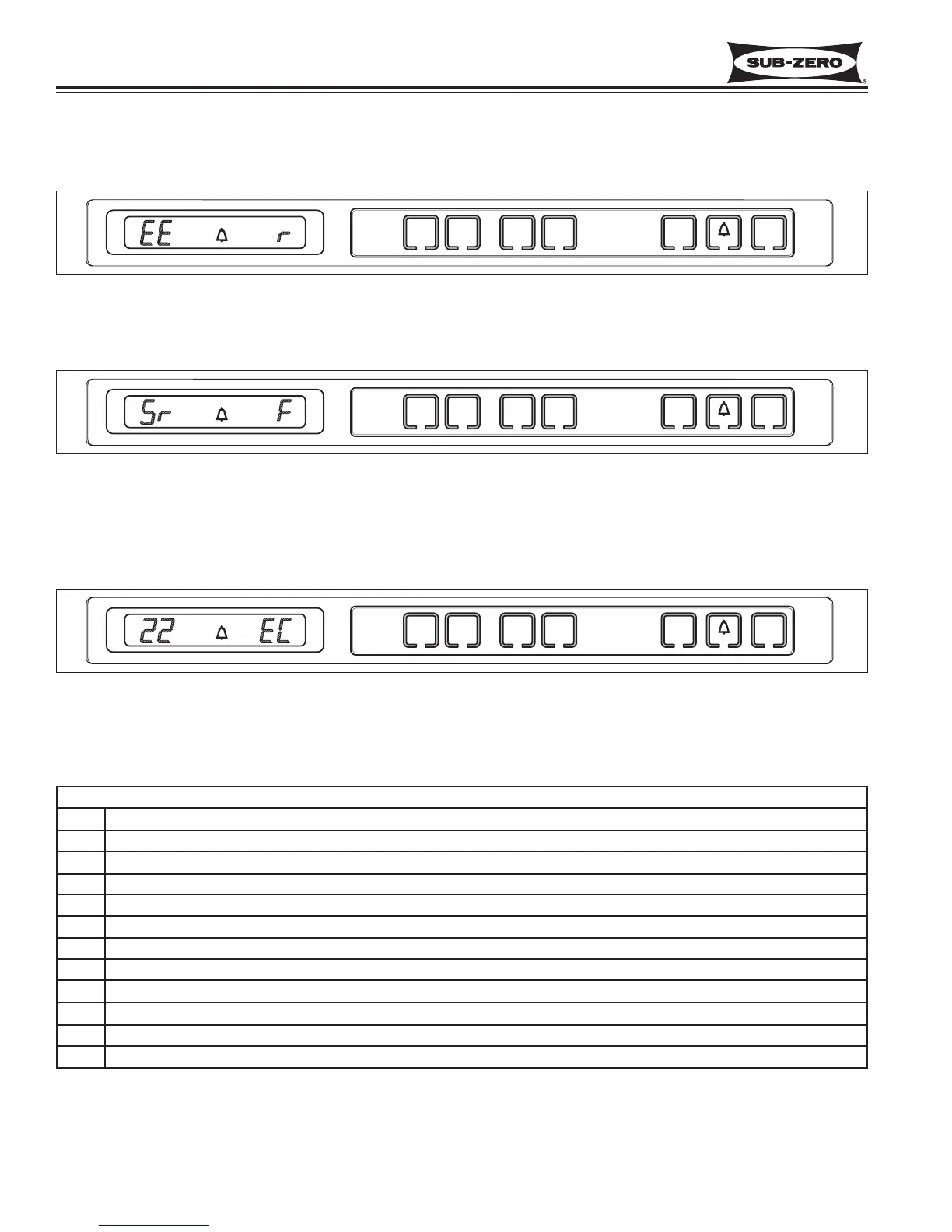
Figure 3-36. “EE” Observed in Diagnostic Mode = Thermistor Fault in Location Indicated by Code
Figure 3-37. “Sr” Observed While in Diagnostic Mode = Unit is in Showroom Mode
If “Sr” is observed at left display area during Diagnostic Mode, the unit is in Showroom Mode, which was explained
earlier in this section (See Figure 3-37).
If “EC” is observed in the right display area during Diagnostic Mode, the numbers at left are “Error Codes” (See
Figure 3-38). Error Codes indicate problems registered by specific components. If error codes are registered, they
will appear before temperature readings and can be toggled through with the temperature readings as described on
the previous page. (See Error Code Table below and instructions on clearing Error Codes on next page.)
Figure 3-38. “EC” Observed While in Diagnostic Mode = Error Code
(See table below & how to clear Error Codes on next Page)
700BCI-3 Error Code Table
CODE INDICATION
05 Refrig. cabinet thermistor read open or shorted for 10+ seconds, or repeatedly read erratic temp’s
07 Freezer cabinet thermistor read open or shorted for 10+ seconds, or repeatedly read erratic temp’s
08 Freezer evaporator thermistor read open or shorted for 10+ seconds, or repeatedly read erratic temp’s
20 Defrost under-heat with no voltage feedback through Gray/White wire at defrost start
21 Defrost overheat
22 No voltage feedback through Gray/White wire at defrost start
23 Defrost overheat with no voltage feedback through Gray/White wire at defrost start
24 Defrost under-heat
30 Excessive Icemaker Water Valve Solenoid Activation (Exceeded 15 Seconds)
40 Excessive Freezer Compressor Run
50 Excessive Refrigerator Fan Run
Diagnostic Mode Indicators
If “EE” is observed in left display area during Diagnostic Mode, the thermistor in that location is open or shorted, or
there is a break in that thermistor’s wiring (See Figure 3-36).