Component Access/Removal
Integrated
(700-
3
BASE)
Series
7-14
#3758424 - Revision B - December, 2005
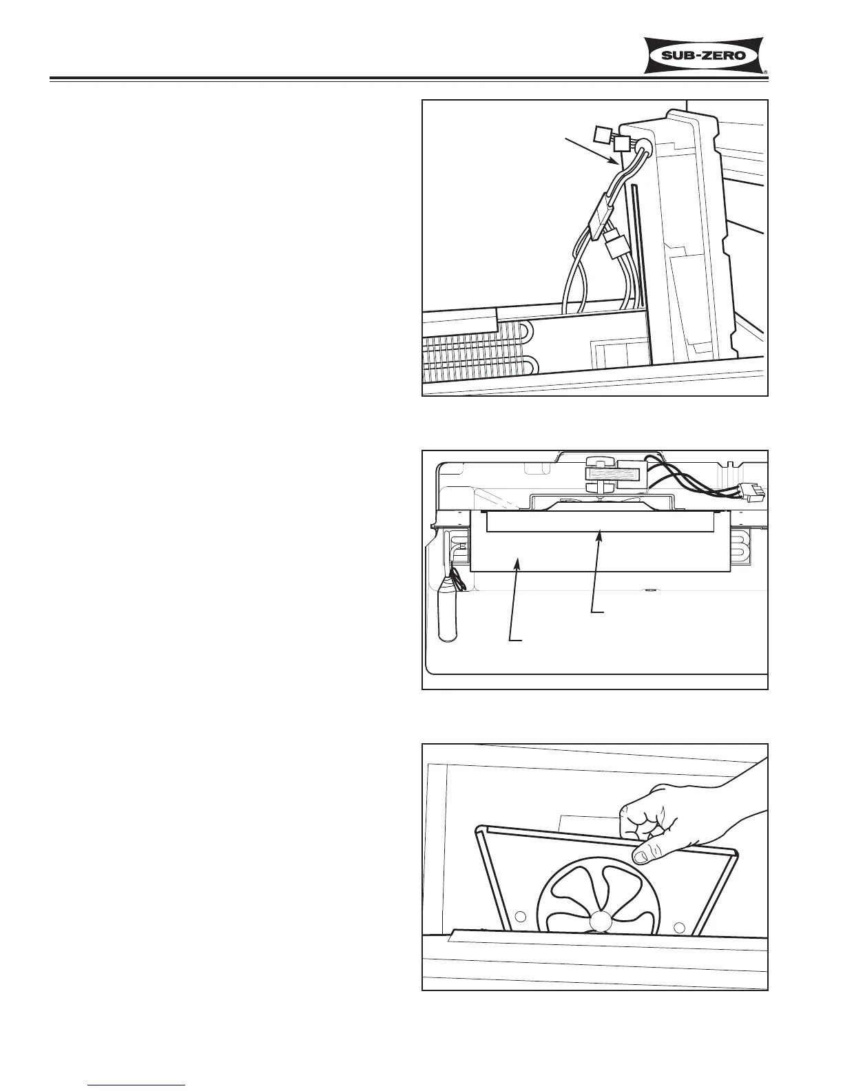
Figure 7-30.
700BCI-3 & 700BFI-3 Evaporator Fan Assembly
Figure 7-29. Top View of 700BCI-3 & 700BFI-3
Evaporator Fan Assembly in Sump
Fan Shroud
Evaporator Fan Assembly
Control Board Assembly
Figure 7-28.
700BCI-3 & 700BFI-3 Control Board Assembly
Control Board Assembly Removal
(700BC/I-3, 700BFI-3 Only)
The control board assembly sets in the right side of
sump. Flanges and grooves on the sides of control
board assembly help to locate it.
To remove the control board assembly (See Figure 7-
28):
1. First remove rear duct(s).
2. Unplug all electrical leads from the control board
assembly and lift the assembly from the sump.
Evaporator Fan Assembly Removal
(700BC/I-3, 700BFI-3 Only)
The side flanges of the evaporator fan assembly slide
down into grooves in the fan shroud. The bottom of the
evaporator fan assembly sits on a flange at the bottom
of the fan shroud. (See Figure 7-29)
To remove the evaporator fan assembly (See Figure 7-
30:
1. First remove rear duct(s).
2. Unplug fan assembly electrical leads and lift assem-
bly up out of the grooves in the fan shroud.
NOTE: Do not attempt to remove the fan assembly
without removing the back duct. Doing so will deform
the back duct and cause air leaks around the air baffle.