Component Access/Removal
Integrated
(700-
3
BASE)
Series
7-20
#3758424 - Revision B - December, 2005
SEALED SYSTEM COMPONENTS
NOTE: When entering the sealed system, always
use solder-on process valves. Do NOT
use bolt-on
process valves as they are prone to leak.
NOTE: Whenever servicing the sealed system, the
high-side filter-drier must
be replaced.
High-Side Filter-Drier Removal (All Base Units)
The high-side filter-drier is located to the right of the
condenser and is attached to the condenser outlet tube
with a cable tie.
NOTE: Before attempting to remove a filter drier, evac-
uate refrigerant from sealed system.
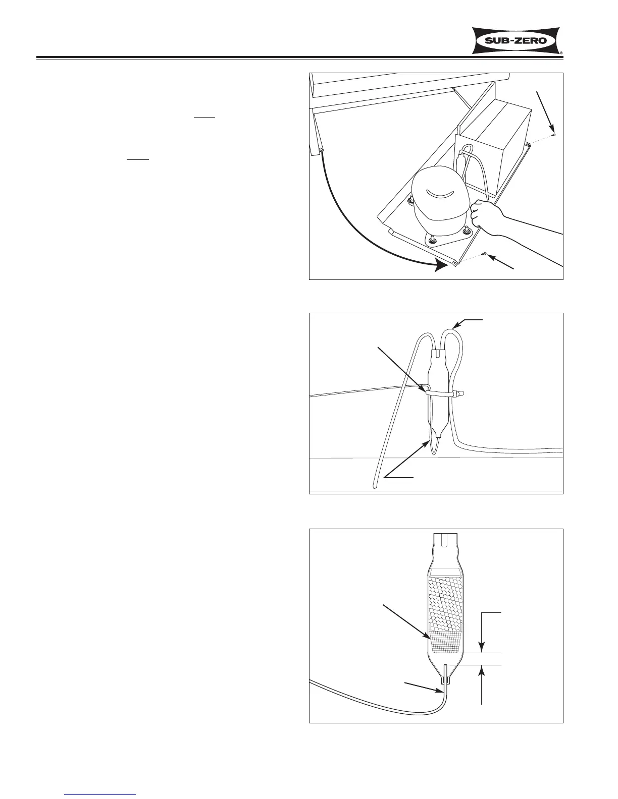
To remove the filter-drier, the kickplate/grill will need to
be removed first. Then, extract the two screws that
secure the unit tray to the unit and slide the tray out
(See Figure 7-43).
NOTE: It may be necessary to disconnect the com-
pressor electrical leads in order to pull the tray out far
enough to access the filter-driers.
To Remove the filter drier (See Figure 7-44):
1. Cut cable tie securing filter-drier to bracket, or con-
denser outlet tube.
2. With the edge of a file, score a line around capillary
tube approximately one inch (25 mm) from filter-
drier outlet
3. Fatigue capillary tube at line just scored until it sep-
arates.
4. With a tube cutter, cut inlet tube approximately one
inch (25 mm) from filter-drier.
NOTE: Sweating the joints apart is not recommended
as this may induce moisture into the sealed system and
could cause a solder restriction in the capillary tube.
NOTE: Check the end of the remaining capillary tube
for internal burrs. If burrs exist, rescore a line around
the capillary tube approximately one inch from the end
and fatigue the capillary tube at this new line until it
separates.
NOTE: When installing the replacement filter-drier,
insert the capillary tube until it touches the screen, then
pull the capillary tube approximately 3/8” away from the
screen before brazing (See Figure 7-45). When
installing a new filter-drier, be sure to thoroughly clean
the tubing before brazing.
Figure 7-43. Sliding Unit Tray Out
Figure 7-44. Filter-Drier Removal