Electronic Control System
Integrated
(700-
3
BASE)
Series
3-3
#3758424 - Revision B - December, 2005
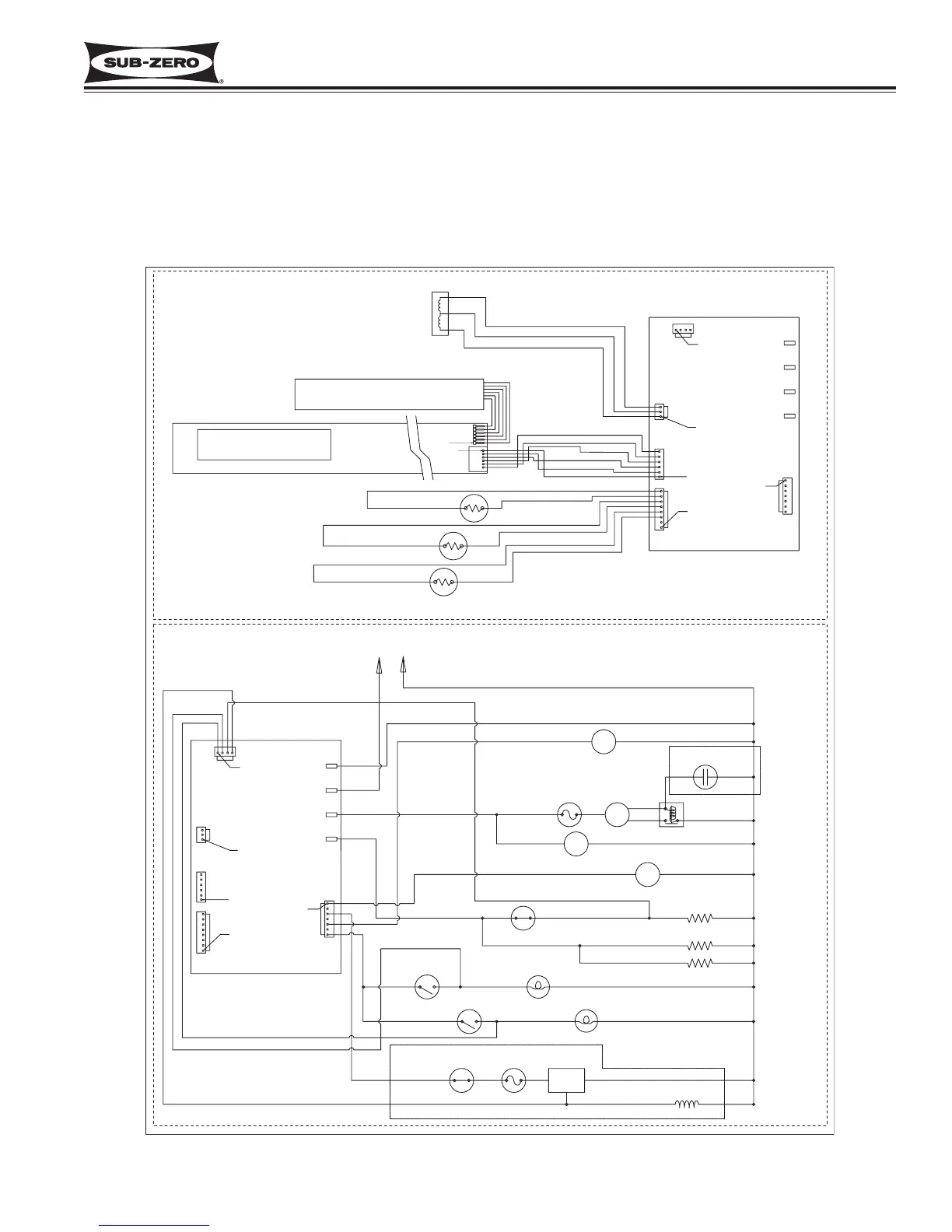
Figure 3-1. 700BCI-3 Wireing Schematic
ELECTRONIC CONTROL SYSTEM OVERVIEW
This page contains the wiring schematic of the model 700BCI-3. Input operations for the electronic control system
are performed at the control panel (located inside the upper drawer), with monitoring, regulating and controlling func-
tions taking place at the main control board. Temperatures and possible problems with the unit are shown in the
control panel display. The entire electronic control system is described in greater detail on the following pages.
NOTE: For more detailed electrical diagrams refer to the wiring diagram and schematic supplied with the unit.