Sealed System Information
Integrated
(700-
3
BASE)
Series
4-4
#3758424 - Revision B - December, 2005
SEALED SYSTEM
OPERATION
The six diagrams on these
pages illustrate a basic sealed
system. The components are
listed in order of refrigerant
flow, with an explanation of
their fundamental role as part
of a sealed system.
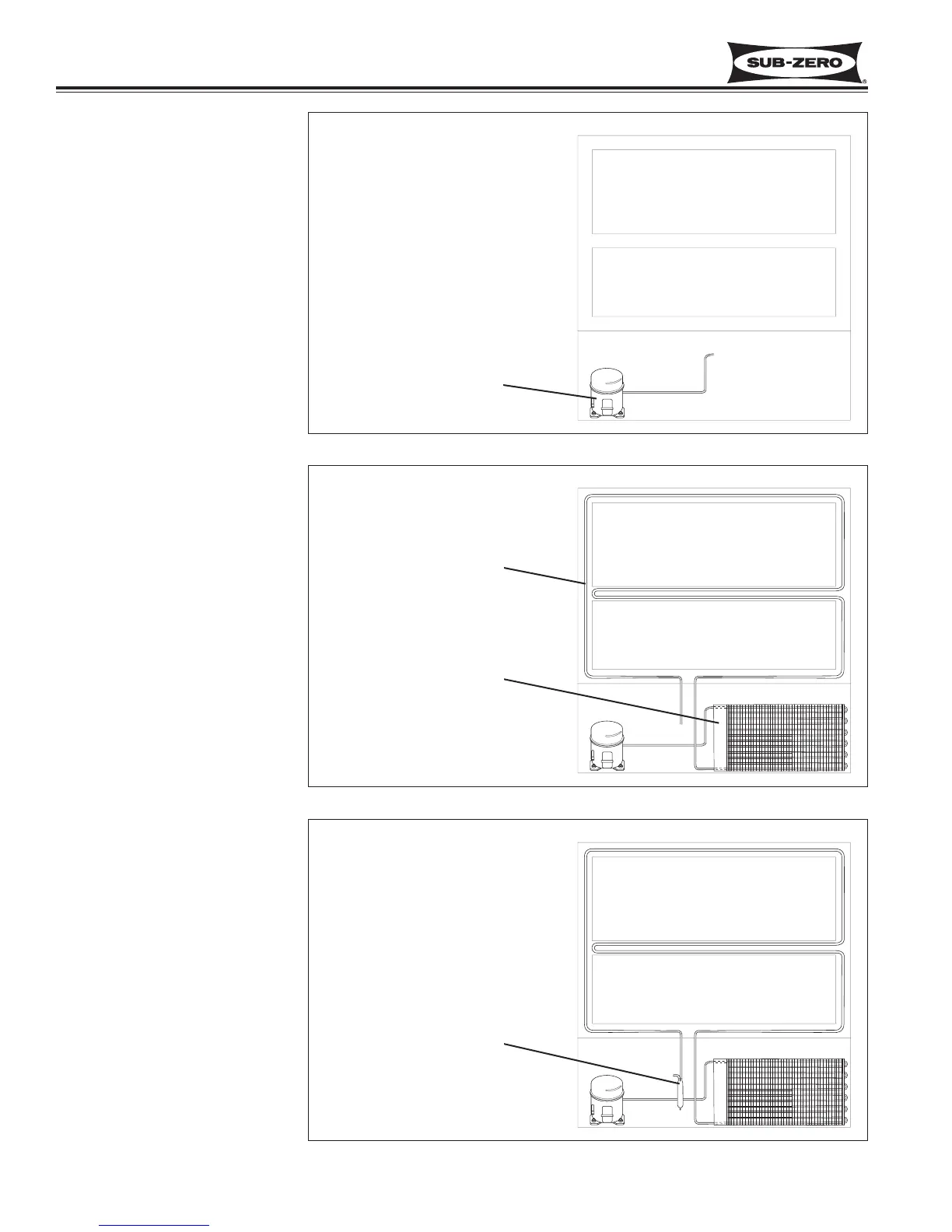
Compressor (Figure 4-1)
The compressor creates a high
side and low side pressure dif-
ference in the sealed system
by compressing the refrigerant
gas, thus raising the pressure
and temperature. The com-
pressor pushes this high-pres-
sure/high-heat gas to the con-
denser.
Condenser (Figure 4-2)
The high-pressure/high-heat
gas travels through the con-
denser, where the heat is dissi-
pated by cooler air being drawn
over the condenser tubing by
the condenser fan. This
changes the gas into a high-
pressure/warm liquid that is
then routed through the door
gasket seat heater loop to pre-
vent sweating. After traveling
through the heater loop, the
high-pressure/warm liquid
enters the high-side filter-drier.
Filter-Drier (Figure 4-3)
The high-pressure/warm liquid
travels through the high-side fil-
ter-drier, which removes mois-
ture from the refrigerant before
it enters the capillary tube.
Figure 4-1. Compressor
Figure 4-3. Filter-Drier
Figure 4-2. Condenser & Heater Loop
COMPRESSOR
CONDENSOR
HEATER LOOP
FILTER-DRIER