Electronic Control System
Integrated
(700-
3
BASE)
Series
3-14
#3758424 - Revision B - December, 2005
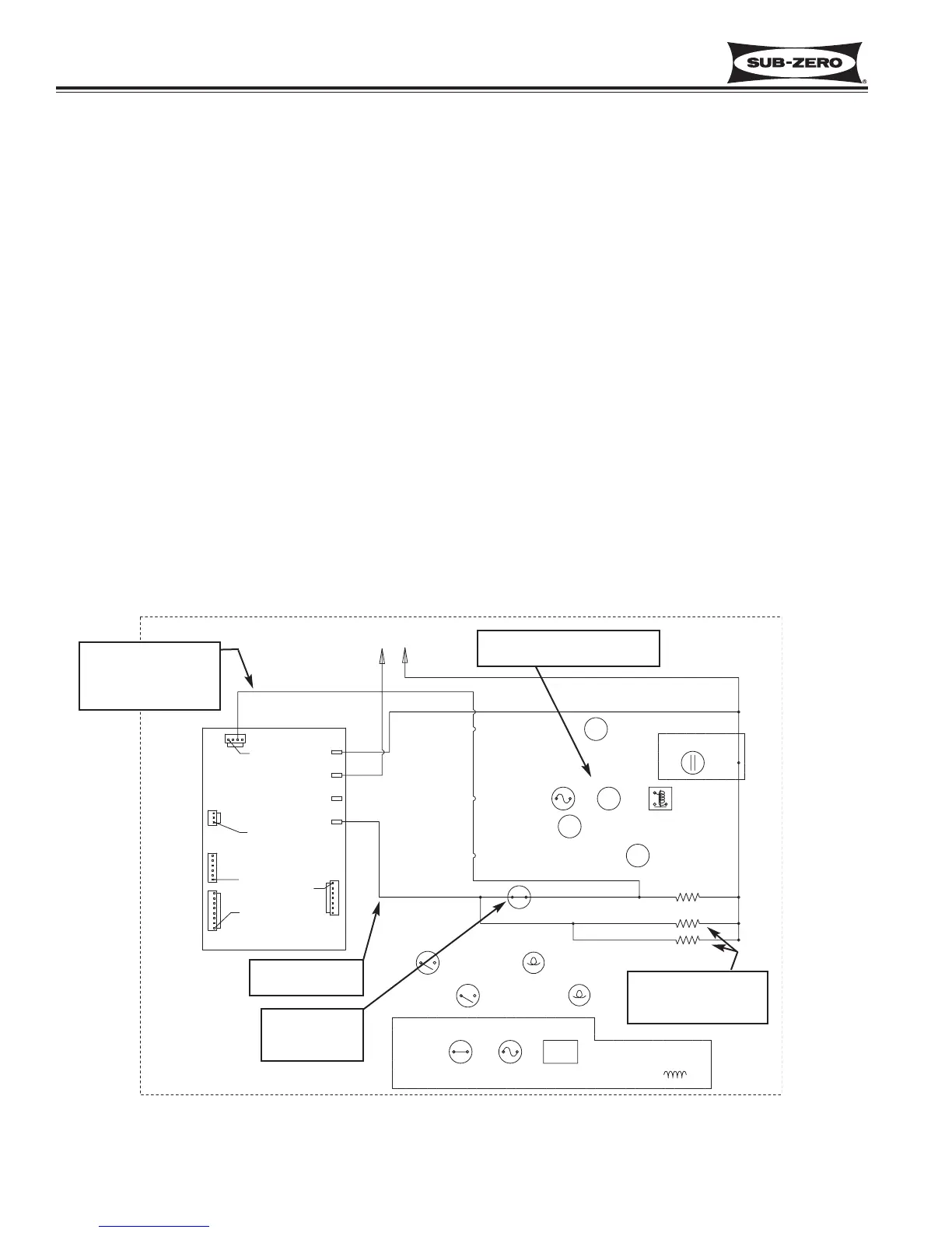
Monitor and Control “Adaptive Defrost” (700BCI-3, 700BFI-3)
Initially, the compressor will cycle-run for 12 hours, after which the microprocessor sends a signal to the defrost relay
on the control board to close. This supplies power to the defrost heater, drain tube heater and fill tube heater. At
the same time the compressor, condenser fan and evaporator fan are switched off.
With the “Adaptive Defrost” technique, the length of time that the defrost heater stays on to open the defrost termina-
tor bimetal (70°F/21°C), is observed by the microprocessor via the grey w/white stripe wire to J2.
The microprocessor then determines the number of hours before the next defrost. If the heater stays on for a short-
er time than specified, the microprocessor increases the next defrost interval. If the heater stays on longer than
specified, the electronic control decreases the next defrost interval. (See Figure 3-13) This is an ongoing process
whereby the defrost time and the defrost interval will vary by unit use.
NOTE: A 5 minute time delay/dwell follows all defrosts, during which the drain tube heater and fill tube heater
remain energized. At the end of the 5 minute dwell, the drain tube heater and fill tube heater are switched off, then
the compressor and condenser fan are energized, but the evaporator fan will not be energized until the evaporator
temperature falls below 35°F (2°C).
NOTE: The minimum defrost interval is 6 hours of compressor run time; the maximum defrost interval is 42 hours of
compressor run time; the maximum defrost duration is 25 minutes plus 5 minute dwell.
NOTE: If the grey w/white wire defrost sensing line is open, defrost operation defaults to 25 minute defrost time and
6 hour build time, and Error Code 22 is logged. If the evaporator thermistor detects an underheat or overheat situa-
tion at the same time, Error Codes 20 or 23 will be registered, respectively.
NOTE: During defrost, the display temperature is locked.
Figure 3-22. 700BCI-3 Signal Trace Schematic - Adaptive Defrost