Component Access/Removal
Integrated
(700-
3
BASE)
Series
7-24
#3758424 - Revision B - December, 2005
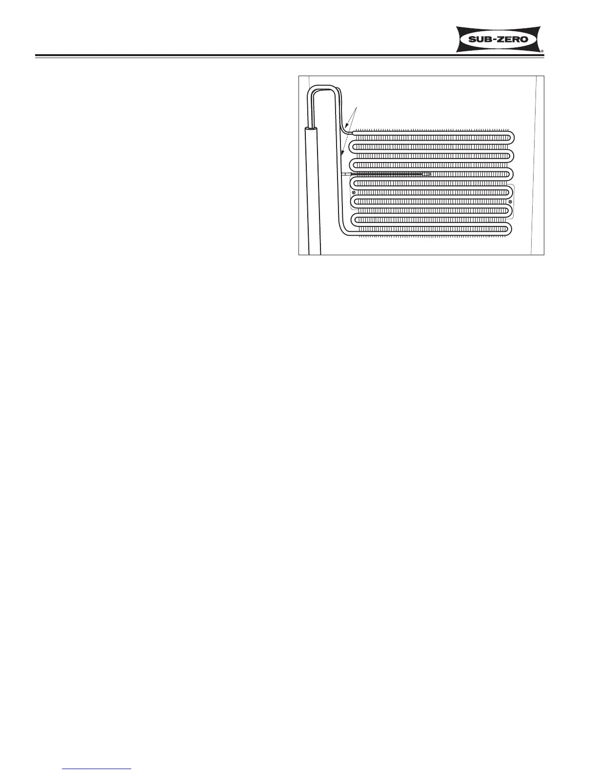
Evaporator Removal (700BR-3 Only)
The evaporator is attached to the rear walls of the com-
partments with screws.
NOTE: Before attempting to remove the evaporator,
evacuate the refrigerant from the sealed system.
To remove the refrigerator evaporator (See Figure 7-
54):
1. Extract screws which hold evaporator to rear wall
of compartment.
2. Pull and rotate evaporator so heat exchanger is
accessible.
3. With a file, score a line around capillary tube, 1” (25
mm) or less from evaporator inlet, then fatigue cap-
illary tube at this line until it separates.
4. With a tube-cutter, cut evaporator outlet 1” (25 mm)
or less from suction line connection point.
NOTE: It is not recommended to sweat tubing apart.
Doing so will induce moisture into the sealed system.
NOTE: After capillary tube is fatigue until it separates,
check tubing for internal burrs. If burrs exist, repeat
step 3 above.
NOTE: Sweating the joints apart is not recommended
as this may induce moisture into the sealed system and
could cause a solder restriction in the capillary tube.
NOTE: When installing replacement evaporator, be
sure to thoroughly clean tubing before brazing.
Figure 7-54. 700 BR-3 Refrigerator Evaporator
Cut