Assembly & Installation
Stabilizer Kit Trolley Pivot Assembly
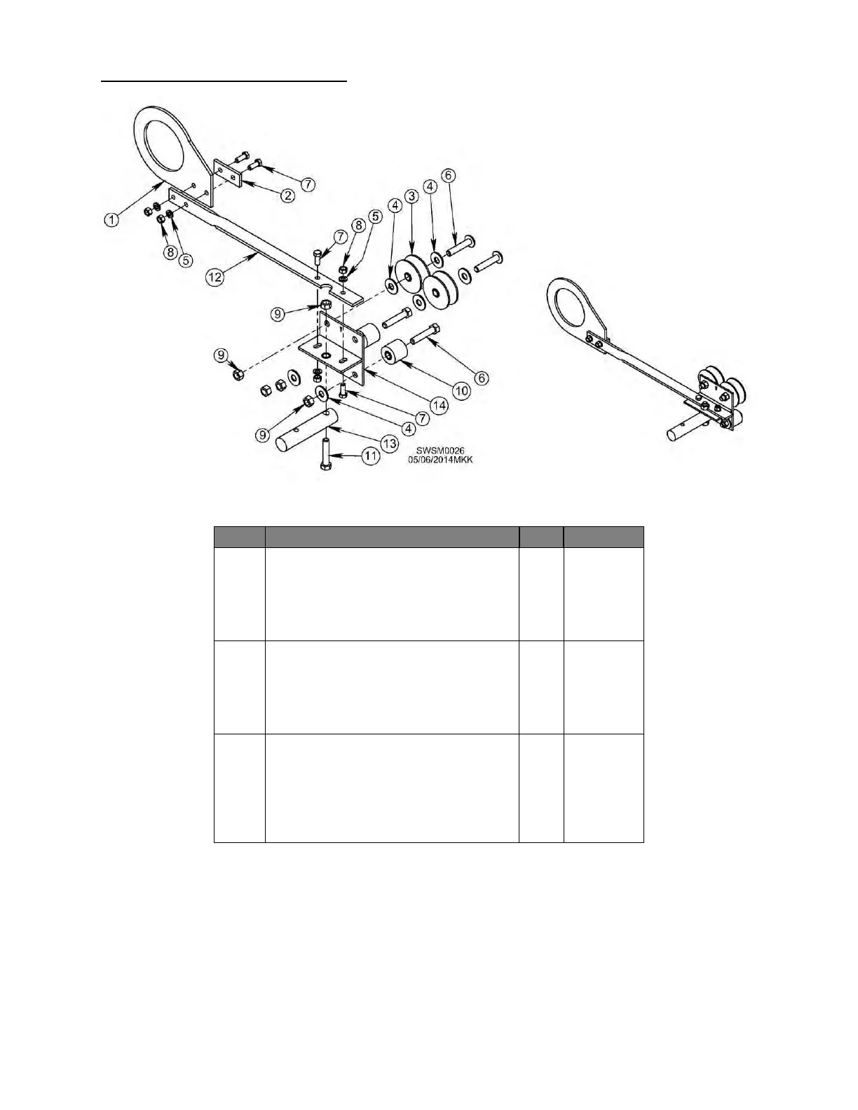
Figure 15 - Assembly of Stabilizer Kit Pivot Assembly, Exploded View
Table 8 - Stabilizer Kit Trolley Pivot Assembly Parts List
Bracket, Plate, Trolley – 4 ½", UHMW
Bracket, Plate, Trolley – 5 ½", UHMW
Wheel, Trolley, w/ Bushings
Bushing, 1/2” x 3/4” x 3/4”
Bushing, 1/2” x 3/4” x 1/2”
Screw, 1/2”-13, 2.5”, GR5, BHCS
Screw, 3/8”-16, 1.25”, PLT
Nut, Hex, Lock, 1/2” - 13
Roller, Trolley, w/ Bushings
Bushing, 1/2” x 3/4” x 1”
Bushing, 1/2” x 3/4” x 1/2”
Screw, 1/2”-13, 2.5”, GR5, BHCS
Bracket, Bar, Pivot Trolley
Shaft, Connect, Pivot Trolley
Bracket, Weldment, Pivot Trolley
15 If your trolley comes pre-assembled, skip to
Step 20.
16 Add a 1/2” flatwasher to each 1/2” x 2-1/2” bolt
and slide a top trolley pulley onto each, adding
second 1/2” flatwasher on outside of pulleys.
Figure 15.
17 Insert 1/2” x 2-1/2” bolt through roller assembly.
Figure 15.
18 Add 1/2” locknut to each bolt. Figure 15.
19 Insert 1/2” x 2-1/2” bolt through hole on
connecting shaft and slide up through center
extended hole on weldment bracket. Add 1/2”
locknut. Figure 15.
20 Insert 3/8” x 1-1/4” bolts through 2 holes trolley
bracket cover, bracket plate, and bracket bar,
adding 3/8” lockwashers and nuts. Figure 15.
21 Bolt bracket bar to weldment bracket using 2 3/8”
x 1-1/4” bolts pointing down through assembly.
Add 3/8” lockwasher and nut. Figure 15.
21.1 Note: Bracket plate fits over crosstube.
22 Tighten all hardware. Ensure roller turns freely.