5-18 Sun StorEdge 3000 Family FRU Installation Guide • May 2004
3. To convert the JBOD to a RAID array, power off the JBOD.
4. Remove all cables connected to the JBOD I/O expansion module(s) which will be
replaced by I/O controller module(s).
5. Remove the top I/O expansion module with the following steps.
a. Turn the thumbscrews on the left and right sides of an I/O expansion module
counterclockwise until the thumbscrews are disengaged from the chassis.
b. Hold the thumbscrews and pull out the I/O expansion module.
c. To remove an SFP, make sure no cable is connected to it and then slide it out
from the port.
Each I/O expansion module has one SFP which can be inserted into the new I/O
controller module and re-used.
6. Insert the SFP from step 5c into the new I/O controller module.
Slide the single-end of the SFP into an empty port so that it connects firmly with the
chassis.
Note – I/O controller module FRUs do not have any SFPs; the SFPs must be
ordered separately. The I/O controller module X-Option includes two SFPs, an
Ethernet cable, and a serial cable.
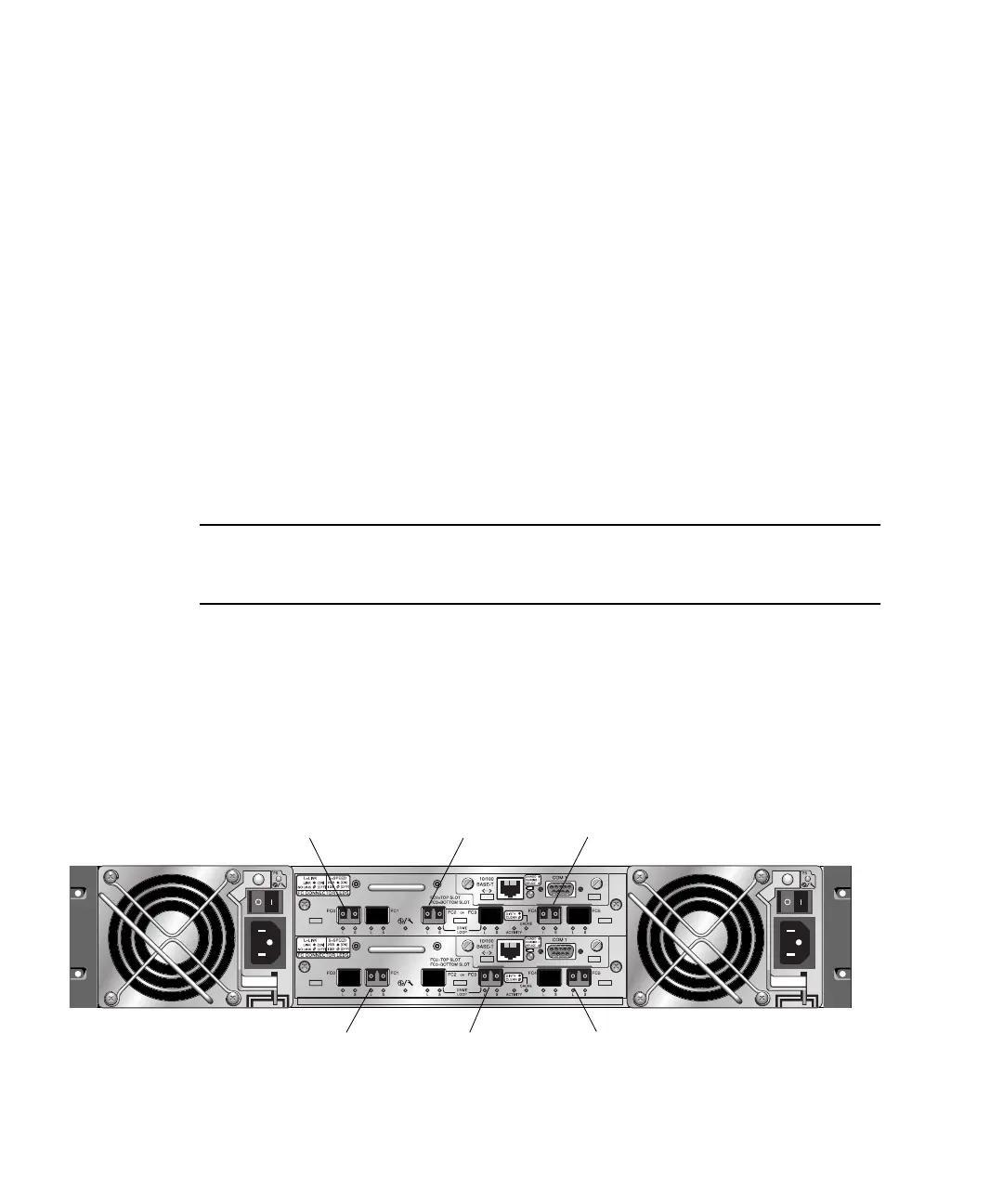
In a dual-controller Sun StorEdge 3510 FC array (
FIGURE 5-7), the recommended
configuration is SFPs plugged into the following ports:
■ The upper I/O controller module with SFPs in the FC0, FC2, and FC4 ports.
■ The lower I/O controller module with SFPs in the FC1, FC3, and FC5 ports.
This configuration provides connections to all four host channels as well as to both
drive channels, and prevents a single point-of-failure.
FIGURE 5-7 Recommended Sun StorEdge 3510 FC Array Dual-Controller SFP Placement
Host port FC0 Drive port FC2 Host port FC4
Host port FC1 Drive port FC3 Host port FC5
 Loading...


