Page | 49
5.15.1. Reactive power setting (QV)
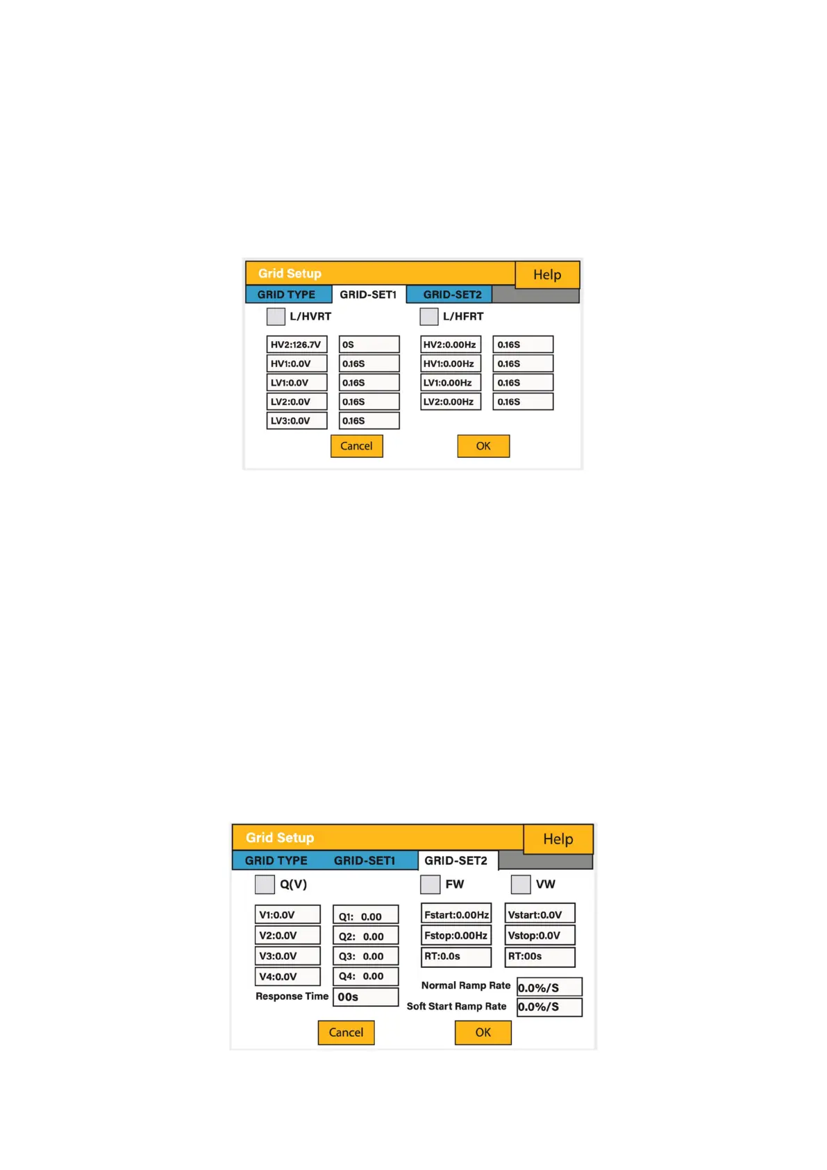
Example: Setting V1=207V and Q1=0.3.
When grid voltage reaches 207V, the inverter will output reactive power at 30% of its
rated power.
5.15.2. Active power setting (VW):
Example: Setting Vstart: 250V and Vstop=260V.
When the grid voltage reaches 250V and gradually increases to 260V, the inverter
output power will gradually decrease. When the voltage reaches to 260V, its output
power will decrease to 20% of P start.
DRMs, logic interface for AS/NZS 4777.2: 2015, is used to receive and response
commands from grid company and then adjust inverter output power.
The power output or input will vary in response to the AC grid voltage. This function is
switched off by default.
1. Click Q (V) for Volt-Var
2. Click VW for Volt-Watt set points, and adjust if needed