MORTEXPRODUCTSINC.501TERMINALRDFORTWORTH,TEXAS76106 Page10
SECTION V: AIR HANDLER INSTALLATION
Installing the Air Handler Unit
Ceiling Installation
If installed in a ceiling, the area in the ceiling where the unit is
to be located should have a framed in structure all around the
unit so the Air Handler unit can be properly mounted and
secured. The ceiling must be 12 inches in height. Prior to
installing the furnace make sure the holes are cut into the frame
for the refrigerant tubing, the drain line, the electrical wiring, the
thermostat wiring and the condenser control wiring. Care should
be taken to insure unit is level to permit proper condensate
drainage.
To properly install the cased horizontal Air Handler unit you
must do the following:
1. Remove the top shipping cover and corner posts.
2. Remove the bottom shipping cover.
3. Remove the control box access panel.
4. Use screws to secure the four (4) straps to the ceiling where
the horizontal Air Handler unit will be installed. Be sure the
straps are located so the hooks in the straps line up with the
slots in the base of the horizontal Air Handler unit.
5. Raise the horizontal Air Handler unit into the space where it
is going to be installed and put the hooks into the slots in
the base. Bend the hooks back to keep the hooks from
slipping out of the slots in the base.
6. Connect the supply air plenum to the horizontal Air
Handler unit as described in cased Air Handler supply duct
connections.
7. If the louvered ceiling access panel is not being used and
solid ceiling access panels is being used then, connect the
return air plenum to the horizontal Air Handler unit as
described in cased Air Handler return air duct connections.
8. Connect the electrical supply wires and the thermostat
control wires in the control box. Be sure to install an
ON/OFF switch in the supply circuit to disconnect the
power during servicing.
9. Connect the refrigerant lines or chilled water lines to the
coil.
10. Re-install the ceiling access panel and control box access
panel and secure with the screws that were removed in step
2
11. Turn the power on to the unit by following the procedure in
the Users Information Manual.
12. Set the thermostat to the desired temperature.
To properly install the un-cased horizontal Air Handler unit you
must do the following:
1. Remove the top shipping cover and corner posts.
2. Remove the screws from the control box cover and remove
the cover.
3. Remove the bottom shipping cover.
4. Use four (4) lag bolts with washers to go thru the slots in
the top cover that secure the horizontal Air Handler unit to
the ceiling where the horizontal Air Handler unit will be
installed.
5. Raise the horizontal Air Handler unit into the space where it
is going to be installed and install the lag bolts thru the slots
in the top cover. Tighten the lag bolts until the horizontal
Air Handler unit is securely fastened to the ceiling.
6. Connect the supply air plenum to the horizontal Air
Handler unit as described in cased Air Handler supply duct
connections.
7. Connect the electrical supply wires and the thermostat
control wires in the control box. Be sure to install a
ON/OFF switch in the supply circuit to disconnect the
power during servicing.
8. Connect the refrigerant lines or chilled water lines to the
coil.
9. Install the control box access panel and secure with the
screws that were removed in Step 2.
10. Install the ceiling access panel and secure to the ceiling
frame with the thumb screws.
NOTE: Ceiling Access Panel is shipped separately. It is not
included with the Air Handler Unit.
11. Turn the power on to the unit by following the procedure in
the Users Information Manual.
12. Set the thermostat to the desired temperature.
SECTION VI: COOLING AND REFRIGERANT
PIPING
DX Cooling / Chilled Water Cooling
DX Refrigerant Piping:
Horizontal Air Handler Units with DX type evaporator coils
require liquid and suction piping sized in accordance with
condensing unit manufacturer’s instructions. The evaporator
coils have sweat copper connections. Refrigerant lines should be
soldered with silver solder or high temperature brazing alloy.
Suction line must be insulated to avoid condensate from forming
and dropping off. Armaflex (or equivalent) with 3/8” (1 cm)
minimum wall thickness is recommended. In severe conditions
such as hot or high humidity areas require 1/2” (1.3 cm)
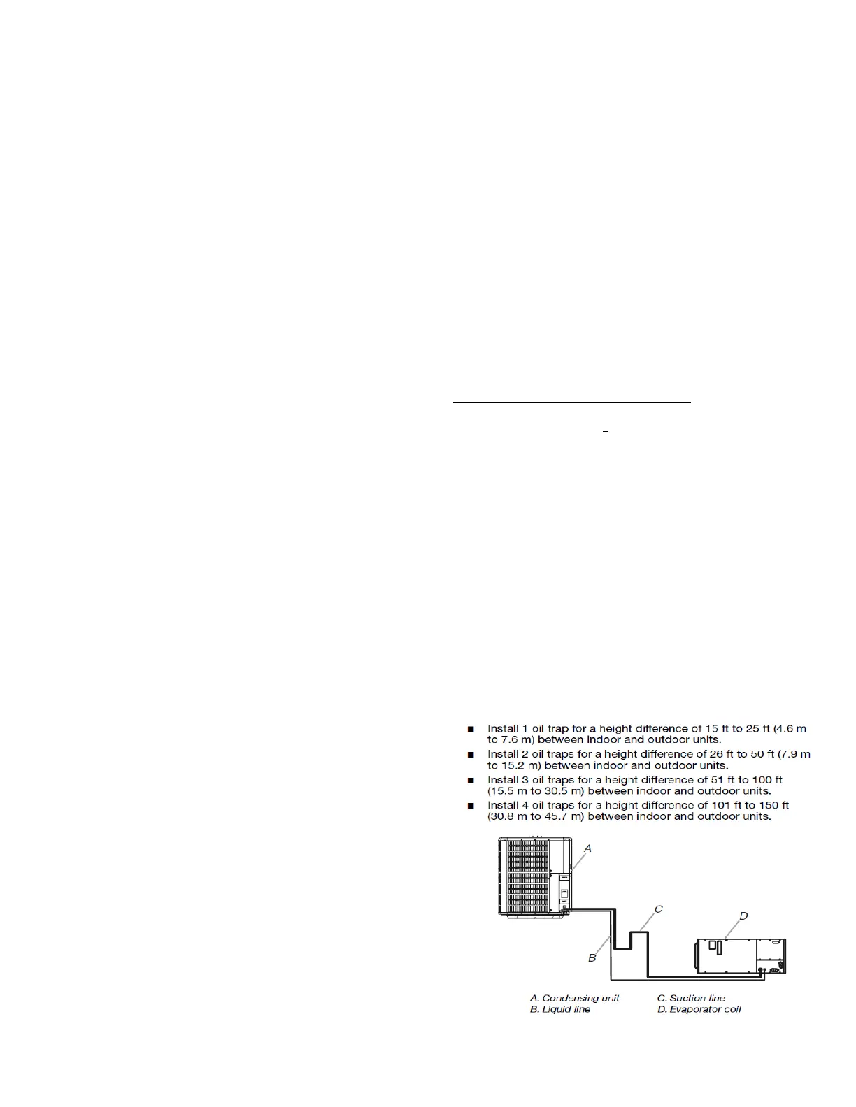
minimum wall thickness may be required. If condensing unit is
installed above evaporator coil then oil traps are required at
equal intervals along suction line (see Figure 6). Horizontal
suction lines should slope 1 inch for every 20 feet toward
condensing unit. Manufacturer recommends that dry nitrogen be
flowed through refrigerant lines during soldering operation.
Figure 6 Evaporator Below Condenser Piping