MORTEXPRODUCTSINC.501TERMINALRDFORTWORTH,TEXAS76106 Page13
Field Installed:
1. After coil pressure has been relieved, turn the female swivel
nut counter-clockwise to remove.
2. If Flowrator Distributor Assembly is being replaced by a
TXV, remove the piston orifice from the flowrator
distributor assembly using a small diameter wire or paper
clip.
3. Attach the TXV by connecting the female swivel nut on
TXV outlet to the flowrator distributor (aligning Teflon seal
first) and torque swivel nut to 10-30 ft. lbs.
4. Attach liquid line with female swivel nut to male rotalock
fitting on TXV inlet (Aligning Teflon seal first) and torque
swivel nut to 10-30 ft. lbs.
5. Remove the cap on Schrader valve port on coil manifold.
Attach equalizer tubing with 1/4” female flare nut that
includes depressor to this male Schrader port. Torque nut
to 10-30 ft. lb
6. Install the TXV bulb to the suction manifold of coil or the
suction line using the two bulb clamps furnished with kit.
a. Bulb should be installed on a horizontal run of the
manifold if possible. On line less than 7/8” OD the
bulb may be installed on top of the line. With 7/8” OD
and over, the bulb should be installed in a position at
about 4 or 8 o’clock.
b. If bulb installation is made on a vertical run, the bulb
should be located at least 6 inches from any bend, and
on the tubing side opposite the plane of the bend. On
vertical bulb installations, the bulb should be
positioned with the bulb capillary tube at the top.
c. The bulb should be insulated using thermal insulation
to protect it from the effect of the surrounding ambient
temperature.
7. After completing installation of TXV (including equalizer
tube), it will be necessary to leak check the coil and
evacuate the coil through the service access fittings of
liquid and suction line valves.
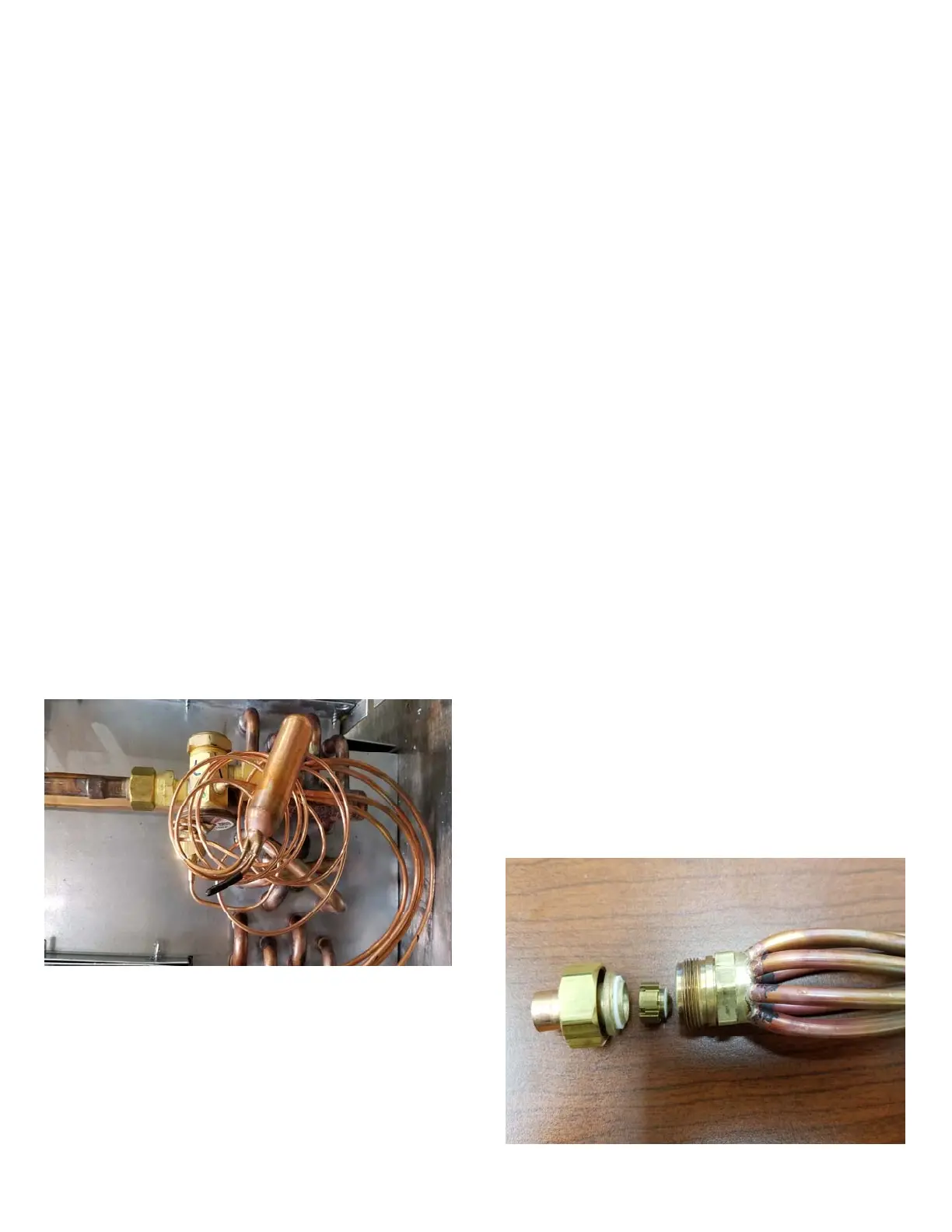
Figure 9 Typical TXV Connections
SPECIAL INSTRUCTIONS FOR COILS WITH
FLOWRATOR DISTRIBUTOR ASSEMBLIES
The sizing of the orifice piston should be based strictly on the
rated capacity of the outdoor unit and coil match.
Summit provides capacity performance ratings that match both
same size and upsized coils with specific manufacturer’s
outdoor units. At the Summit distributor’s request, the orifice
piston is selected and installed in each coil for the specific range
of cooling capacities likely to be encountered. The factory
installed orifice piston size is marked on the flowrator
distributor assembly and on the front of the coil carton.
When using this coil with an outdoor unit of another capacity,
select an orifice piston from the table below if the capacity
range for the coil and outdoor unit to be used differs.
Failure to install the proper orifice piston can lead to poor
system performance and possible compressor damage. A
variation of one piston size is not normally critical. Summit
reserves the right to substitute a factory installed piston one size
smaller or greater if the piston size ordered is out of stock.
A selection of replacement orifice pistons is available from your
Summit supplier.
FLOWRATOR TO TXV CONVERSION:
While thermal expansion valves can be factory installed, they
are normally available in kit form for field installation. For kit
version, follow the installation instructions provided with the
kit. Normally these can be field installed before system is
charges without requiring cutting and brazing. BE SURE
FLOWRATER PISTON HAS BEEN REMOVED FROM
THE FLOWRATER DISTRIBUTOR BODY PRIOR TO
INSTALLATION OF EXPANSION VALVE.
ORIFICE PISTON REPLACEMENT:
If the flowrator distributor assembly is being used the piston is
to be installed as shown in Figure 10 in the distributor body then
the existing liquid line attached to the flowrator distributor.
1. After coil pressure has been relieved, turn the female swivel
nut counter-clockwise to remove.
2. Remove the piston from the flowrator distributor fitting
using a small diameter wire or paper clip. ALWAYS
REMOVE PISTON FROM DISTRIBUTOR BODY
WHEN TXV IS INSTALLED).
3. Replace the orifice piston with the correct piston for the coil
you are using. Make sure the tapered end of the piston is
facing the feeder tubes on the distributor body.
4. Turn the female swivel nut on clockwise the flowrator
distributor (aligning Teflon seal first) and torque swivel
nut to 10-30 ft. lbs.
5. After completing the replacement of the orifice piston, it
will be necessary to leak check the coil and evacuate the
coil through the service access fittings of liquid and suction
line valves.
Figure 10: Flowrator Distributor