MORTEXPRODUCTSINC.501TERMINALRDFORTWORTH,TEXAS76106 Page24
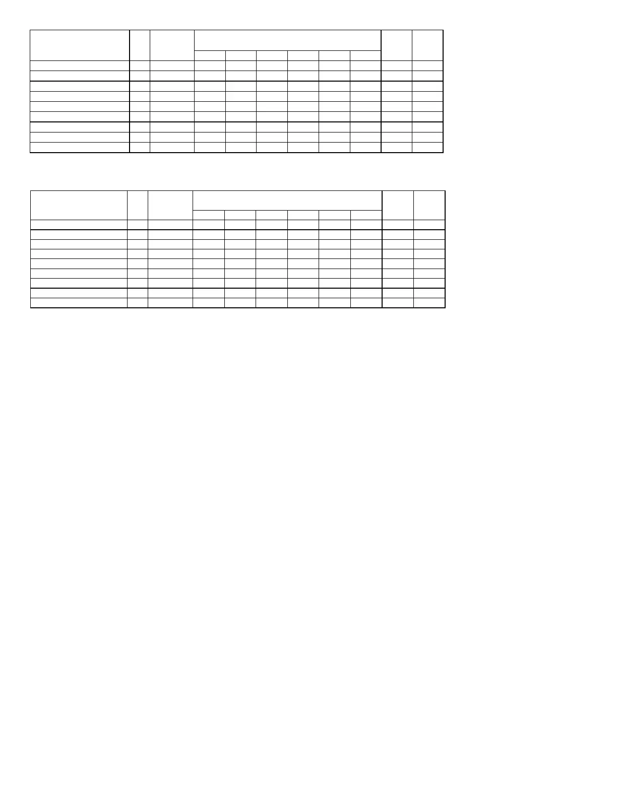
13
°
F14
°
F15
F16
F170
F180
F
SDXW/CDXW-18-21-0A-0A78 2 PSC 18,000 21,100 24,200 27,300 30,500 33,600 3.0 3.3
SDXW/CDXW-19-22-0E-0A78 2 PSC 19,200 22,500 25,800 29,100 32,400 35,800 3.0 3.3
SDXW/CDXW-24-23-09-0A78 2 PSC 19,300 22,700 26,000 29,400 32,700 36,100 3.0 3.3
SDXW/CDXW-30-27-0J-0A70 2 PSC 23,700 27,800 32,000 36,000 40,100 44,300 3.0 3.3
SDXW/CDXW-31-28-05-0A70 2 PSC 23,900 28,000 32,200 36,300 40,500 44,600 3.0 3.7
SDXW/CDXW-34-30-0K-0A70 2 PSC 25,300 29,600 33,900 38,300 42,700 47,100 3.0 3.7
SDXW/CDXW-35-30-0K-0A70 2 PSC 25,400 29,800 34,000 38,500 42,900 47,300 3.0 3.7
SDXW/CDXW-36-32-OK-0A70 2 PSC 27,200 31,800 36,500 41,200 45,900 50,600 3.0 4.2
SDXW/CDXW-37-32-01-0A70 2 PSC 27,500 32,200 36,900 41,600 46,300 51,100 3.0 4.2
Heating
GPM
(2) Max.
Fuses
Model Number
Coil
Rows
Type Of
Blower Motor
Heating Capacities
Entering Water Temperatures
Table 24: SDXW/CDXW Hot Water Capacity Using Two Row Hot Water Coil– 120 VAC PSC Blower Motor - 18-37 BTU/H
Models
130
°
F 140
°
F 150
F 160
F 170
F 180
F
SDXW/CDXW-18-21-0A-0A78 2 C.T 18,000 21,100 24,200 27,300 30,500 33,600 3.0 3.3
SDXW/CDXW-19-22-0E-0A78 2 C.T 19,200 22,500 25,800 29,100 32,400 35,800 3.0 3.3
SDXW/CDXW-24-23-09-0A78 2 C.T 19,300 22,700 26,000 29,400 32,700 36,100 3.0 3.3
SDXW/CDXW-30-27-0J-0A70 2 C.T 23,700 27,800 32,000 36,000 40,100 44,300 3.0 3.3
SDXW/CDXW-31-28-05-0A70 2 C.T 23,900 28,000 32,200 36,300 40,500 44,600 3.0 3.7
SDXW/CDXW-34-30-0K-0A70 2 C.T 25,300 29,600 33,900 38,300 42,700 47,100 3.0 3.7
SDXW/CDXW-35-30-0K-0A70 2 C.T 25,400 29,800 34,000 38,500 42,900 47,300 3.0 3.7
SDXW/CDXW-36-32-OK-0A70 2 C.T 27,200 31,800 36,500 41,200 45,900 50,600 3.0 4.2
SDXW/CDXW-37-32-01-0A70 2 C.T 27,500 32,200 36,900 41,600 46,300 51,100 3.0 4.2
Heating
GPM
(2) Max.
Fuses
Model Number
Coil
Rows
Type Of
Blower Motor
Heating Capacities
Entering Water Temperatures
Table 25: SDXW/CDXW Hot Water Capacity Using Two Row Hot Water Coil– 120 VAC Constant Torque Blower Motor - 18-37
BTU/H Models
SECTION VIII: LINE VOLTAGE WIRING
Power Supply Wiring
The unit internal wiring is complete except for the power supply
and the thermostat wires. See wiring diagram and/or Tables 26-
29 for wire size, fuse/circuit breaker size, and ground wire sizes.
The use of cable connectors on incoming power supply wires to
relieve any strain on wiring is recommended. Follow the steps
below to connect the power supply wires.
Line Wiring Connections
1. Remove the thumb screws that secure Ceiling Access Panel
and slowly swing the panel down to access the Air Handler
unit.
2. Remove the screws that secure the control box access panel,
and then remove the access panel.
3. Install the cable connectors on the 7/8” dia hole on the
bottom right side of the control box.
4. Strip ½” of the insulation on the end of each wire.
5. Insert the wires through the cable connector located in the
7/8” diameter hole in the Air Handler control box flange.
6. The supply power wires are connected to the two (2) pole
terminal block or pigtails located on the right side of the
control box.
7. Insert the black wire into the L1 screw terminal on the two
(2) pole terminal block and tighten the set screw to clamp
down on the wire.
8. Insert the white or red wire into the L2 screw terminal on
the two (2) pole terminal block and tighten the set screw to
clamp down on the wire.
9. Insert the green wire into the ground lug and tighten the
set screw.
General wire and breaker sizes are shown in Tables 26-29. If
sheathed cable is used, refer to NEC National Electrical Code
(NFPA 70) or the Canadian Electrical Code, Part I (CSA C22.1)
and local codes for additional requirements concerning supply
circuit wiring. Electrical data can be found in Tables 26-29.
IMPORTANT - All installation on field wiring must be rated at
60ºC or higher. Please refer to the wiring diagrams on the
furnace or the tables this manual for more information.
Refer to the NEC National Electrical Code (NFPA 70) or the
Canadian Electrical Code, Part I (CSA C22.1) and local codes
for wiring material requirements.