MORTEXPRODUCTSINC.501TERMINALRDFORTWORTH,TEXAS76106 Page33
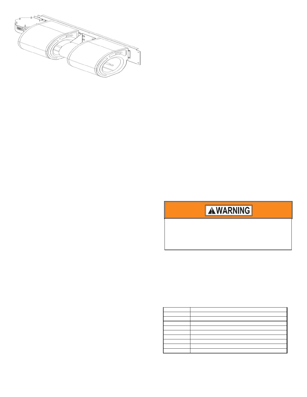
Figure 32: Constant Torque Blower Assembly
13 Remove both of the blower housings by sliding the blower
wheels “off” the motor shaft.
14 Replace both of the blower housings by sliding the blower
wheels “on” the motor shaft.
15 Set the new blower motor on the mount bracket. Place one
end of the retaining clip into the notch on the motor mount
bracket. Use a straight edge screw driver and a mallet on
the “U” shaped part of the retaining clip to push the clip
down and into the notch on the other side of the bracket.
16 Set the blower housing in the correct position on the blower
mount plate and secure the blower housings with the screws
that were removed.
17 Rotate the blower housing so you are looking at the wheel
from the discharge of the blower. Center the blower wheels
in the housing then use a hex key to tighten the set screws
and secure the blower wheels to the motor shaft.
18 Grab the blowers and lift the panel up, push in on the
bottom, then pull down to set the blower mount plate in
place.
19 Replace the two screws on the blower mount plate located
on the right side, the left side, the screw on the top center
and the screw in the control box. Refer to Figures 31 and 32
for screw locations.
20 Place the motor wires into the control box and replace the
strain relief that is securing the wires to the control box.
21 Reconnect the blower motor power wires from the relay
and the terminal block.
22 Replace the control box cover and secure with the screws
that were removed.
23 Close the ceiling access panel and secure the panel with the
thumb screws that were removed.
24 Turn on all electrical supply circuits to the Air Handler unit
at the main service (House Circuit Breaker) panel.
25 Set the thermostat to the desired temperature.
Typical Heat Pump - Heating/Cooling Thermostat Wiring
Connections
1. Remove the blower access panel.
2. Remove the control box cover.
3. Install a grommet or a strain relief in the 9/16”
diameter hole on the top and the right side of the air
handler casing to protect the thermostat wire cable.
4. Strip ½” of the insulation on the end of each wire.
5. Insert the wire cable from the thermostat thru the 9/16”
hole into the control box and place the thermostat wire
cable next to the low voltage pigtails. Secure the
thermostat wire cable with a strain relief to prevent
wire connections from being pulled apart.
6. Connect the Red (24 VAC) supply wire from the
thermostat to the Red low voltage pigtail wire on the
air handler. Fasten the wires together securely with a
wire nut. If the outdoor unit has a red wire or “R”
terminal then connect the red wire from the outdoor
unit with the Red thermostat wire from the second
cable and connect this red wire to the “RC” terminal on
the thermostat. Fasten the wires together securely with
a wire nut.
7. Connect the White (first stage heating) wire from the
thermostat to the White low voltage pigtail wire on the
air handler and the White wire from the “E” terminal
on the outdoor unit. Fasten the three wires together
securely with a wire nut.
8. Connect the Green (indoor fan) wire from the
thermostat to the Green low voltage pigtail wire on the
air handler and securely fasten the two wires together
with a wire nut.
9. Connect the Red wire from the “Y” terminal on the
outdoor unit. Fasten the three wires together securely
with a wire nut.
10. Connect the brown (24 VAC Common) wire from the
thermostat with the yellow low voltage pigtail wire on
the air handler and with the brown (Common) wire
from the “C” terminal on the outdoor unit. Fasten the
three wires together securely with a wire nut.
11. Connect the Orange (Reversing Valve Solenoid) wire
from the thermostat with the Orange wire from the “O”
terminal on the condenser unit. Fasten the two wires
together securely with a wire nut.
CONSTANT TORQUE MOTOR
Selecting the Constant Torque Blower Speed
This furnace uses the new constant torque high efficiency
motor. This motor operates on 240 VAC. The motor speed tap
are 24 VAC, 0.03 amps, 60 Hz, 1 PH. The speed taps can be
changed by removing the black wire from the blower motor
terminal T5 or the red wire from the blower motor terminal T1
and connecting the wires to T4, T3 or the T2 blower motor
terminals. Table 35 shows the constant torque motor terminals
and the connection definitions.
Terminal Connection
C Speed Tap Common - 24 VAC Common
L Supply Voltage - 240 Vac Line 1
G Ground Connection
N/L2 Supply Voltage - 240 Vac Line 2
1 Low Speed Tap - 24 VAC Input
2 Medium-Low Speed Tap - 24 VAC Input
3 Medium Speed Tap - 24 VAC Input
4 Medium-High Speed Tap - 24 VAC Input
5 High Speed Tap - 24 VAC Input
Table 35: Constant Torque Motor Terminals
Total 24 VAC circuit amps are 0.14 amps.
To avoid personal injury or property damage, make
certain that the motor leads cannot come into
contact with non-insulated metal components of
the unit.