MORTEXPRODUCTSINC.501TERMINALRDFORTWORTH,TEXAS76106 Page32
“C” terminal on the outdoor unit. Fasten the three wires
together securely with a wire nut.
12. Connect the Orange (Reversing Valve Solenoid) wire from
the thermostat with the Orange wire from the “O” terminal
on the condenser unit. Fasten the two wires together
securely with a wire nut.
SECTION X: MOTOR, BLOWER AND AIR
HANDLER STARTUP
Change Motor Speeds - PSC Motor
1. Turn off all electrical supply circuits to the Air Handler
unit at the main service (House Circuit Breaker) panel.
2. Remove the screws from the ceiling access panel and
open the panel to get access to the control box.
3. Remove the screws that secure the control box cover to
the Air Handler unit then, remove the cover.
4. Disconnect the wire from the isolation relay terminal
and reconnect the desired wire to the terminal.
Here is the PSC motor speed tap wire color code:
Black wire is High Speed, Blue wire is Medium Speed,
and Red wire is Low Speed. Brown wires for capacitor.
5. Reinstall control box cover and secure the cover with
the screws that were removed.
6. Close the ceiling access panel and secure with the
screws that were removed.
7. Turn on all electrical supply circuits to the Air Handler
unit at the main service (House Circuit Breaker) panel.
8. Set the thermostat to the desired temperature.
Replacing the Blower Motor
1 Turn off all electrical supply circuits to the Air Handler unit
at the main service panel.
2 Open the ceiling access panel by removing the thumb
screws.
3 Remove the four (4) screws that secure the motor guard to
the control box.
4 Remove the control box cover by removing the two (2)
screws that are securing the cover to the Air Handler unit.
5 Disconnect the blower motor power wires from the relay
and the terminal block.
6 Remove the strain relief that is securing the wires to the
control box and remove the blower motor wires from the
control box.
7 Remove the two screws on the blower mount plate located
on the right side, the left side, the screw on the top center
and the screw in the control box. Refer to Figures 31 and 32
for screw locations.
Figure 29: PSC Blower Assembly
8 Grab the blowers and lift the panel up and pull out on the
bottom. Slide the panel down and out of the Air Handler
chassis.
9 Rotate the blower housing so you are looking at the wheel
from the discharge of the blower. Use a hex key to loosen
the set screws that secure the blower wheels to the motor
shaft.
10 Remove the screws that secure the both blower housings to
the blower mount plate.
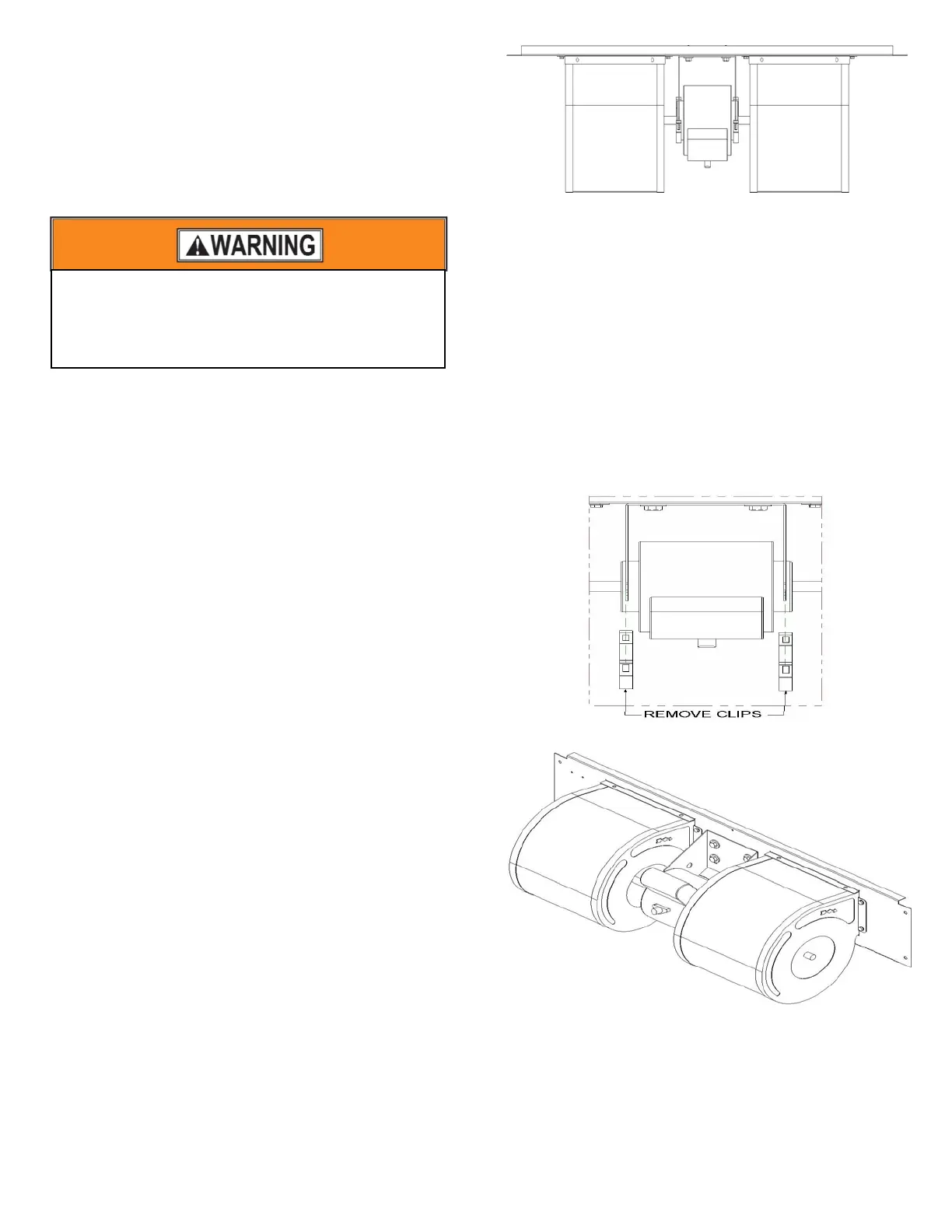
11 Remove the blower motor from the mount bracket by
placing a straight edge screw driver on the “U” shaped part
of the clip. Push the clip down and away from the bracket
to pop the clip off the bracket.
12 After both motor mount retaining clips have been removed;
the motor it can be removed the motor mount plate.
Figure 30: Blower Motor Retainer Clips
Figure 31: PSC Blower Assembly
To avoid personal injury or property damage, make
certain that the motor leads cannot come into
contact with non-insulated metal components of
the Air Handler Unit.