MORTEXPRODUCTSINC.501TERMINALRDFORTWORTH,TEXAS76106 Page27
Figure 19: Component Locations – No Heat Control Box
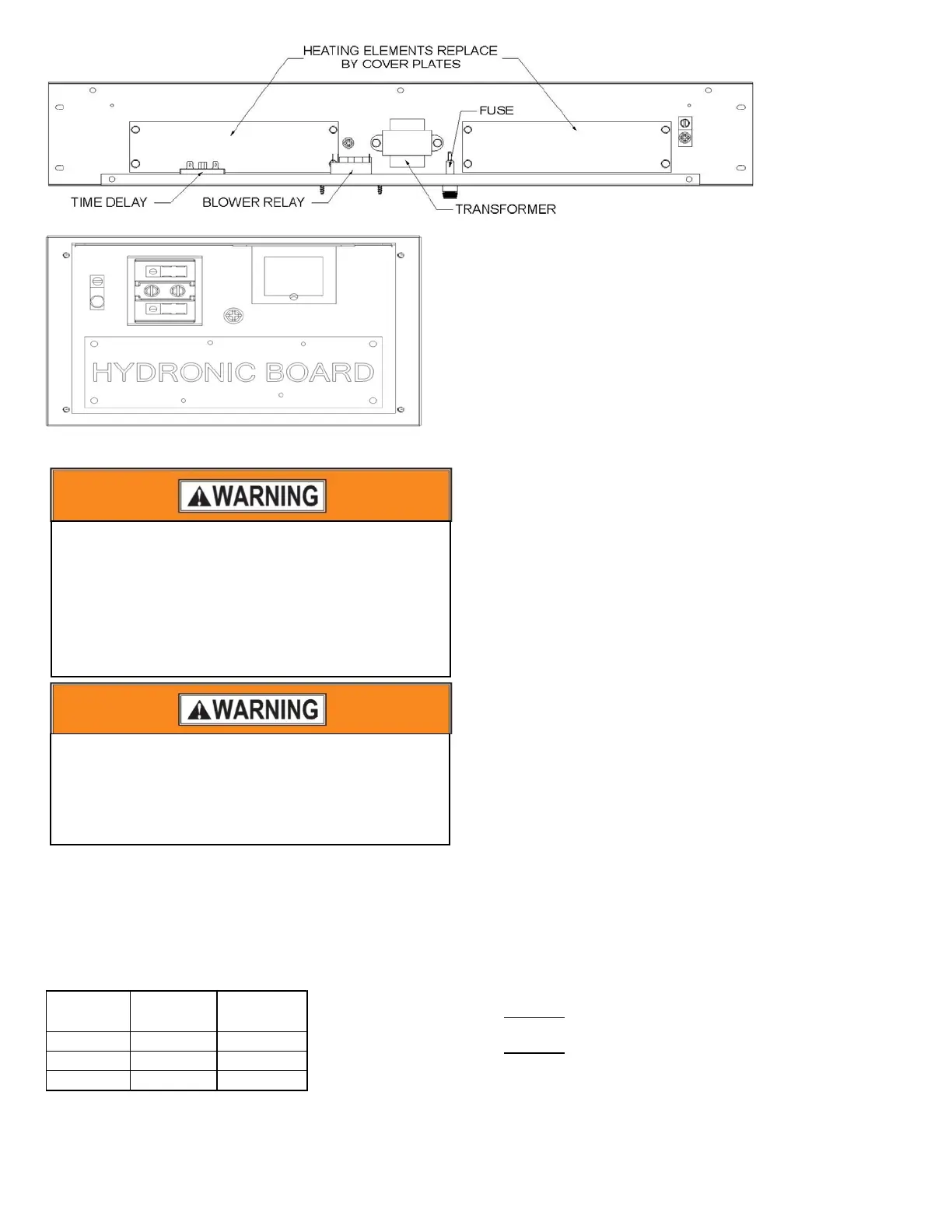
Figure 20: Component Locations – Hydronic Heat Control Box
SECTION IX: THERMOSTAT WIRING AND
CONNECTIONS
Thermostat Wiring
Thermostat wires connect through side of furnace and should be
no smaller than 22 gauge. Refer to Table 30 for recommended
wire gauge, lengths and maximum current for each wire gauge.
Max.Thermostat
WireLength
ThermostatWire
Gauge
ThermostatWire
MaximumCurrent
0‐100Feet 22 3.0Amps
0‐125Feet 20 3.0amps
0‐250Feet 18 3.0amps
Table 30: Low Voltage Wire Gauge and Max Lengths
Thermostat wires can enter through the side of the unit.
When bringing wiring through the side of the Air Handler unit,
cable connectors must be installed to hold wiring in place and to
relieve any strain on the wiring.
The use of a five-conductor cable from the thermostat to the
furnace is recommended for typical heating or heating/cooling
installations with a two or three-conductor cable from the
furnace to the condenser. The thermostat wire colors and the
typical heating/cooling connections are listed in Tables 32 - 34.
A seven-conductor cable from the thermostat to the furnace is
recommended for a typical heat pump installation with a five-
conductor cable from the furnace to the condenser.
The thermostat wire colors and the typical heat pump
heating/cooling connections are listed in Table 34.
Thermostat Installation
The thermostat heat anticipator must be-set at 0.4 Amps if the
thermostat has a manual heat anticipator adjustment. This
setting should be checked at the time of installation.
The thermostat may be a “self-setting" type in which case no
heat anticipator setting will be found on the thermostat,
eliminating the need for any field adjustment.
Thermostat should be located on an inside wall in an open area
to more closely regulate average room air, preferably, where
there is air movement back to furnace. Locating height of
thermostat is important. Thermostat should be located
preferably in a hallway upstream from the furnace return
airflow, not within three feet of from any windows and 52 to 66
inches above the floor.
DO NOT place the thermostat within three feet of any of the
furnace supply air registers
DO NOT
place the thermostat within three feet of any of the air
conditioner supply air registers
Maintenance, operating and/or programming instructions are in
the envelope accompanying the thermostat. Give the envelope to
the home owner.
For personal safety be sure to turn the electrical power
“OFF” at the main entrance (Home Circuit Breaker Box)
and at the unit control box circuit breakers before
attempting any service or maintenance operations.
Homeowners should never attempt to perform any
maintenance which requires opening the Ceiling Access
Panel door. Refer to Figures 4 and 5.
Take precautions to prevent accidental electrical shock. Be
sure to turn the electrical power “OFF” at the main entrance
(Home Circuit Breaker Box) and at the service disconnect
before removing the ceiling access panel. Refer to Figures 4
and 5 for drawin
of the ceilin
access
anel.