MORTEXPRODUCTSINC.501TERMINALRDFORTWORTH,TEXAS76106 Page3
some instances these instructions exceed certain local codes
and ordinances, especially those who have not kept up with
changing home construction practices. These instructions
are to be followed and are the minimum requirement for a
safe installation.
12. The size of the unit should be based on an acceptable heat
loss calculation for the structure. ACCA, Manual J or other
approved methods may be used.
13. The 115 VAC models use nominal 115 VAC, 1 Phase, 60-
Hertz power supply. DO NOT CONNECT THIS
APPLIANCE TO A 50 HZ POWER SUPPLY OR A
VOLTAGE ABOVE 132 VOLTS OR BELOW 98 VOLTS.
14. The 208/230 VAC models use nominal 208 or 230 VAC, 1
Phase, 60-Hertz power supply. DO NOT CONNECT THIS
APPLIANCE TO A 50 HZ POWER SUPPLY OR A
VOLTAGE ABOVE 253 VOLTS OR BELOW 187
VOLTS.
15. Ground connections MUST BE securely fastened to the
control box and ground wires MUST BE secured to the
ground lugs in the control box.
16. Duct work must be installed in accordance with the
standards of the National Fire Protection Association
(NFPA) for the installation of Air Conditioning, Warm Air
Heating and Ventilation Systems (NFPA 90A and 90B).
The air distribution duct should be sized for 0.2 inches of
static pressure. See National Environmental Systems
Contractors Association Manual K for duct sizing.
17. The safety testing label appearing on this unit covers the
unit and the factory installed coil (if provided) only. It does
not cover any other equipment.
18. Exterior surface of the cabinet may sweat when installed in
a non-conditioned space such as an attic or garage. Installer
must provide a protection such as a full size auxiliary drain
pan under all units installed in the non-conditioned space.
The drain pan is needed to prevent damage from
condensation runoff on the unit casing.
19. Cabinet insulation is rated for R-2.1 (standard) Nominal
½”. Some jurisdictions require R-4.2 or R-6.0 on
installations in a non-conditioned space. Add 1” thick
insulation to the exterior casing of the unit to comply in
these jurisdictions, putting the vapor barrier on the outside.
GENERAL INFORMATION
This horizontal Air Handler unit provides the flexibility for
installation in any horizontal application. The versatile models
may be used with or without electric heat. The direct drive three
(3) speed PSC motor or five (5) speed Constant Torque Motor
will provide an air volume to match any application.
The unit can be positioned for bottom or air return through the
end of the unit in the horizontal position.
Inspection
As soon as the furnace is received, it should be inspected for
possible damage during transit. If damage is evident, the extent
of the damage should be noted on the carrier’s freight bill. A
separate request for inspection by the carrier’s agent should be
made in writing. Before installing the air handler you should
check the cabinet for screws or bolts which may have loosened
in transit. Some units have blower motor supports over the
motor shaft. Remove support before operating the horizontal Air
Handler unit.
See local Distributor for more information. Mortex Products,
Inc assumes no liability for freight damage.
Check the connecting of the wiring, electric heater, ducts or
piping to make sure there is easy access to the horizontal Air
Handler unit during the installation.
CASED ENCLOSURE MOUNTING
The installer must adhere strictly to all local and national code
requirements pertaining to the installation of this equipment.
These enclosures are designed to be installed in the ceiling for
horizontal mounting only.
Location of the unit must be in an area providing adequate
access to the ceiling panel since all components must be
serviced from this area.
The enclosure should be lifted to the desired location and
secured using the mounting holes located on the top with an
acceptable mounting method (Figure 1). The enclosure must be
level in both directions to permit proper drainage of the Air
Handler.
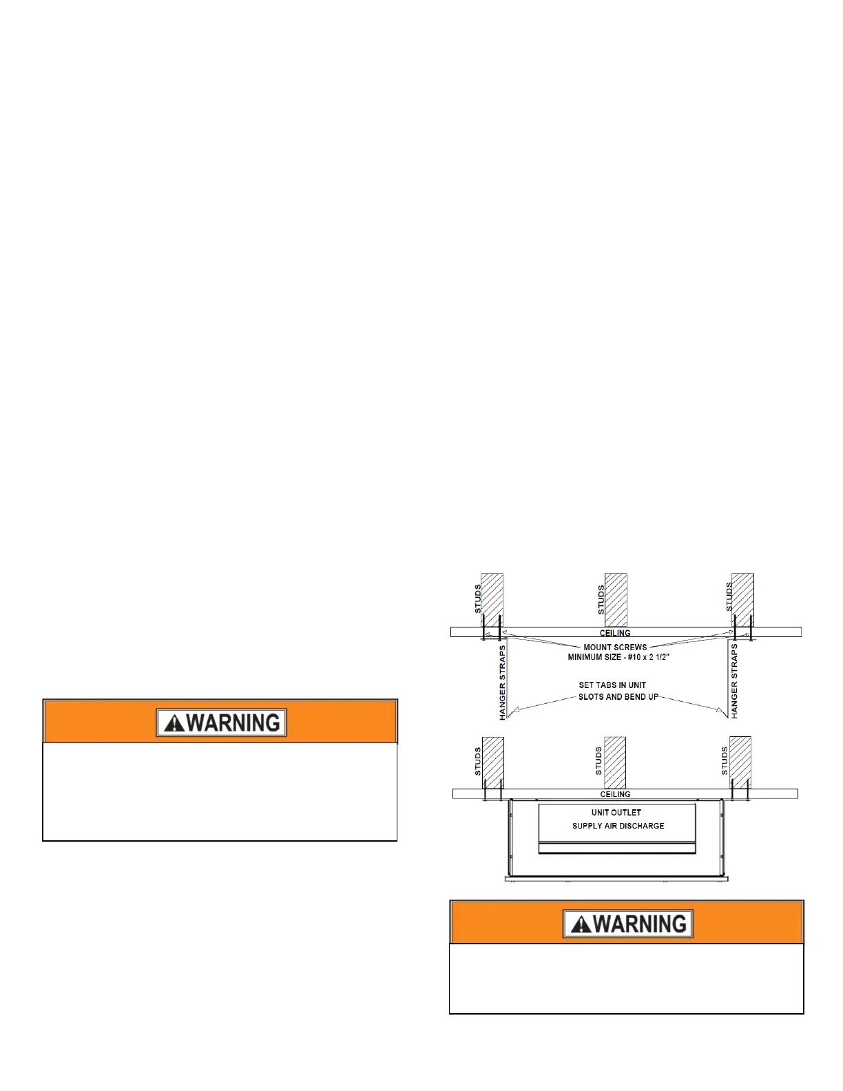
After the enclosure is mounted a 2x2 or 2x4 frame must be
installed around the base of the enclosure to create an air tight
seal and support for ceiling panel frame. Figure 1 shows a
typical arrangement for the framing required.
Figure 1: Cased Enclosure Mounting
ALWAYS SHUT OFF ELECTRICITY AT THE
DISCONNECT SWITCH OR TURN OFF THE CIRCUIT
BREAKERS IN THE MAIN ELECTRICAL ENTRANCE
BEFORE PREFORMING ANY SERVICE ON THE
PPLIANCE.
Extreme caution must be taken that no internal
damage will result if screws or holes are drilled into
the cabinet.