MORTEXPRODUCTSINC.501TERMINALRDFORTWORTH,TEXAS76106 Page31
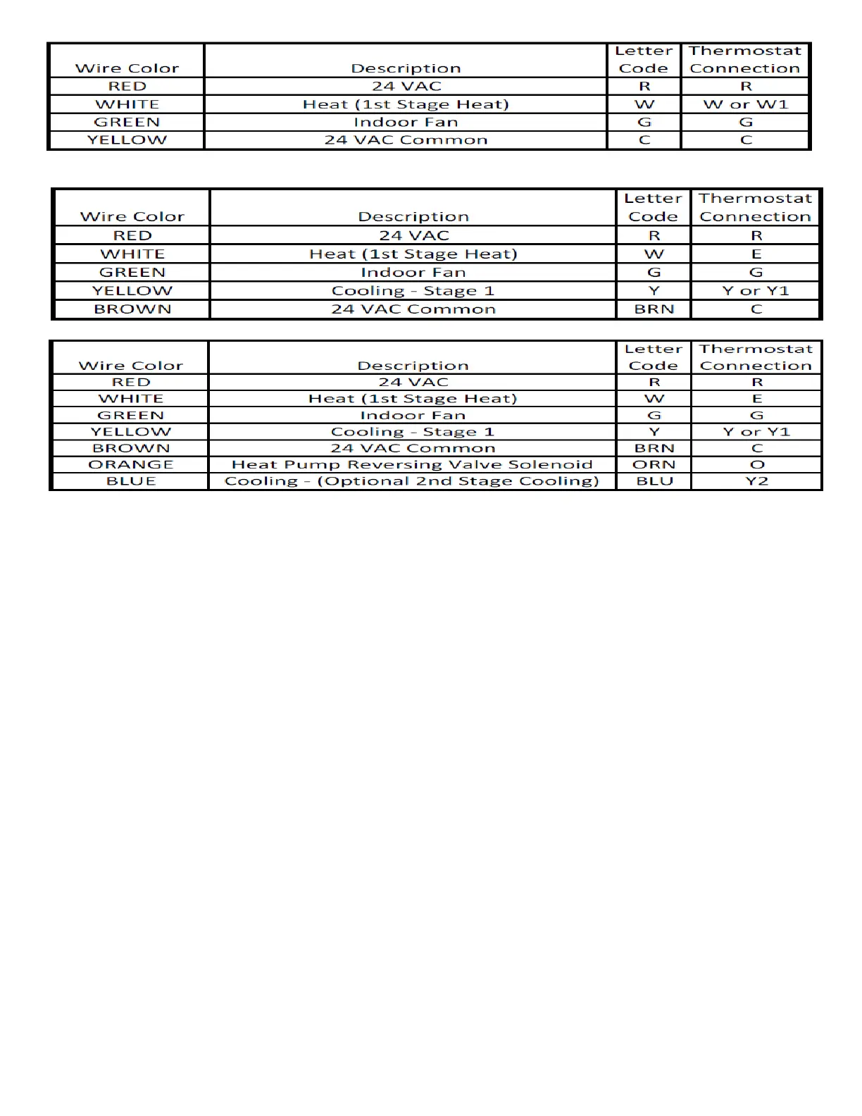
Table 32: Typical Air Handler Unit Thermostat Pigtail Wire Colors and Connections.
Table 33: Typical Cooling Unit Thermostat Wire Color Codes and Connections.
Table 34: Typical Heat Pump Thermostat Wire Color Codes and Connections.
Typical Heating/ Cooling Wiring Connections
1. Remove the ceiling access panel.
2. Remove the control box cover.
3. Install a grommet or a strain relief in the 9/16” diameter
hole on the top and the left side of the Air Handler unit to
protect the thermostat wire cable.
4. Strip ½” of the insulation on the end of each wire.
5. Insert the wire cable from the thermostat thru the 9/16” hole
into the control box and place the thermostat wire cable
next to the low voltage pigtails. Secure the thermostat wire
cable with a strain relief to prevent wire connections from
being pulled apart.
6. Connect the Red (24 VAC) supply thermostat wire to the
Red low voltage pigtail wire and secure with a wire nut.
7. Connect the White (First stage heating) thermostat wire to
the White low voltage pigtail wire and secure with a wire
nut.
8. Connect the Green (Indoor fan) thermostat wire to the
Green low voltage pigtail wire and secure with a wire nut.
9. Connect the Yellow (Air conditioning) wire from the
thermostat to the compressor contactor on the condenser
unit.
10. Connect the brown (24 VAC Common) wire from the
thermostat with the yellow low voltage pigtail wire on the
Air Handler unit and with the brown (Common) wire from
the compressor contactor on the outdoor unit. Fasten the
three wires together securely with a wire nut.
Typical Heat Pump/Heating/Cooling Wiring Connections
1. Remove the ceiling access panel.
2. Remove the control box cover.
3. Install a grommet or a strain relief in the 9/16” diameter
hole on the top and the left side of the Air Handler unit to
protect the thermostat wire cable.
4. Strip ½” of the insulation on the end of each wire.
5. Insert the wire cable from the thermostat thru the 9/16” hole
into the control box and place the thermostat wire cable
next to the low voltage pigtails. Secure the thermostat wire
cable with a strain relief to prevent wire connections from
being pulled apart.
6. Connect the Red (24 VAC) supply wire from the thermostat
to the Red low voltage pigtail wire on the air handler and
with the Red wire from the “R” terminal on the outdoor
unit. Fasten the three wires together securely with a wire
nut.
7. Connect the White (first stage heating) wire from the
thermostat to the White low voltage pigtail wire on the air
handler and the White wire from the “E” terminal on the
outdoor unit. Fasten the three wires together securely with a
wire nut.
8. Connect the Green (indoor fan) wire from the thermostat to
the Green low voltage pigtail wire on the air handler and
securely fasten the two wires together with a wire nut.
9. Connect the Red wire from the “Y” terminal on the outdoor
unit. Fasten the three wires together securely with a wire
nut.
10. Connect the Yellow (Air conditioning) wire from the
thermostat to the compressor contactor on the condenser
unit.
11. Connect the brown (24 VAC Common) wire from the
thermostat with the yellow low voltage pigtail wire on the
Air Handler and with the brown (Common) wire from the