MORTEXPRODUCTSINC.501TERMINALRDFORTWORTH,TEXAS76106 Page7
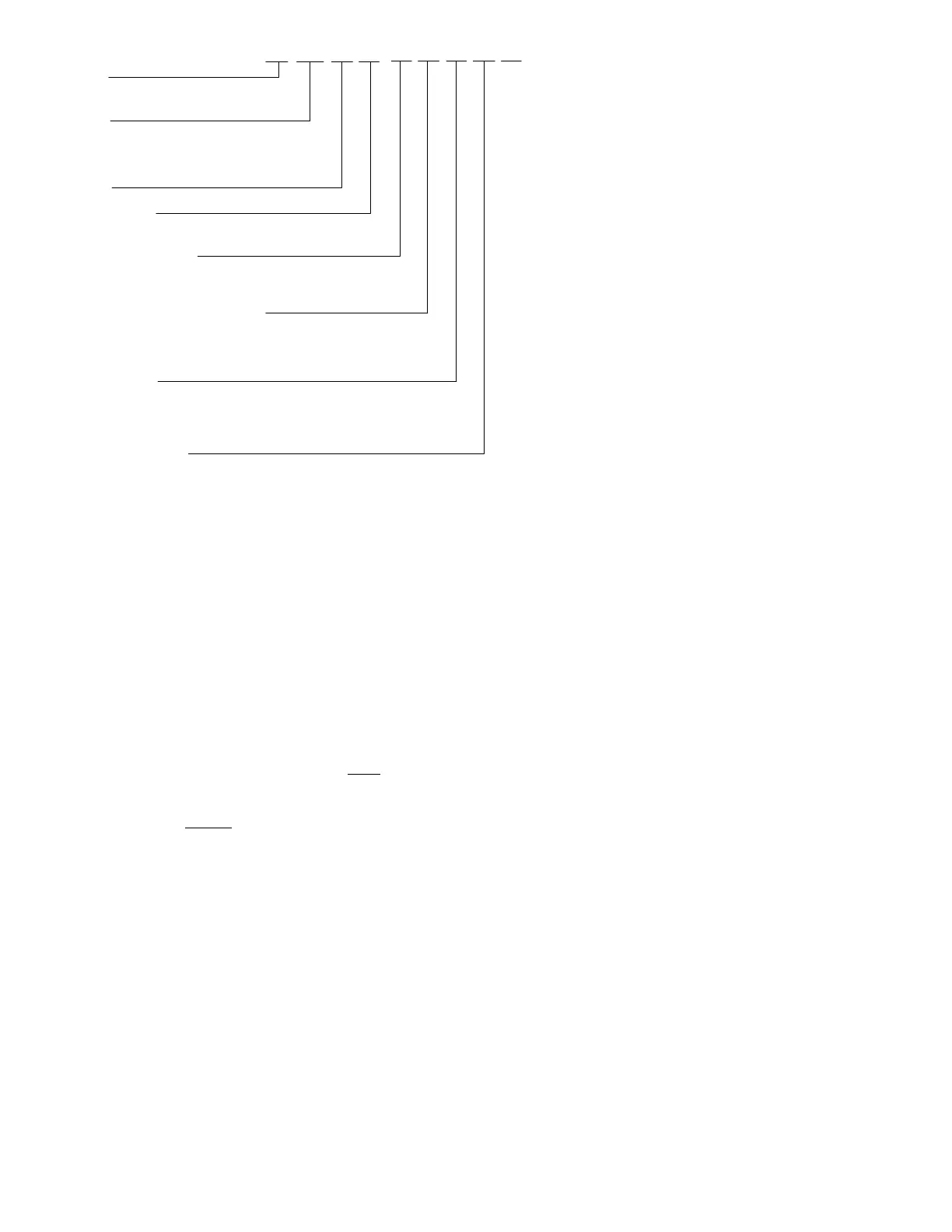
EHXS
2 4
0 3
ED1
C
79
SERIES
S - Horizontal Firdown Unit Uncased
C - Horizontal Firdown Unit Cased
TYPE
EHX - DX Coil and Electric Heat
CWE - Chilled Water Coil and Electric Heat
DXW - DX Coil and Hot Water Heat
CWW - Chilled Water Coil and Hot Water Heat
Tons
Nominal Cooling BTUH
Heating Capacity
03 - Electric Heat Capacity in kW
26 - Hot Water Heat Capacity in M/BTUH
Orifice or Expansion Valve Number
D - TXV4-A (E410A 1.5 to 2.5 Ton)
Y - TXV4-A (R410A 3.0 Ton)
Expansion Device Code
E = Expansion Valve (DX)
Time Delay Relay
1 - With TDR (Standard)
Unit Voltage
A - 115/1/60
C - 208/240/1/60
Motor & Wheel Code
65 - 1/4 HP, 208/240V, PSC, with (2) 6.25x8.00
70 - 1/4 HP, 115V, PSC, with (2) 6.25x8.00
78 - 1/4 HP, 115V, PSC, with (2) 6.25x6.88
79 - 1/4 HP, 240V, PSC, with (2) 6.25x6.88
80 - 1/3 HP, 208/230V, CT, with (2) 7.00x8.00
81 - 1/2 HP, 208/240V,CT, with (2) 7.00x9.00
82 - 1/3 HP, 115V,CT, with (2) 7.00x8.00
83 - 1/2 HP, 115V,CT, with (2) 7.00x9.00
2 = 2 Pipe Chilled Water (CW)
4 = 4 Pipe Chilled Water (CW)
4 - 4 Row Chilled Water Coil (CW)
5 - 5 Row Chilled Water Coil (CW)
Table 11: SEHX/CEHX/SCWE/CCWE/SDXW/CDXW/SCWW/CCWW Model Nomenclature
SECTION IlI: CLEARANCE AND RETURN
AIR REQUIREMENTS
LOCATION
Access for servicing is an important factor in the location of any
Air Handler unit. Provide a minimum of 27 inches under the
appliance for access to the control box, heating elements, water
pump, blower and air filters. The unit can be serviced entirely
from the bottom of the unit, including replacing the air filter on
models that include a filter rack. These units are NOT
designed
to be installed in a closet or flush mounted in a wall in an up
flow vertical position. The Air Handler unit is designed for
horizontal application ONLY.
Be sure to route primary and secondary drain connections
so as not to obstruct replacement filter.
Location is usually predetermined. Check with owner’s or
dealer’s installation plans. If location has not been decided,
consider the following in choosing a suitable location.
1. Select a location with adequate structural support, space for
service access, clearance for return and supply duct
connections. Unit is designed to fit in a 12” high drop down
space (Furred-In Area).
2. Where normal operating sound levels may be objectionable
if the Air Handler is placed directly over or under some
rooms such as bedrooms, study, etc.
3. Caution should be taken to locate the Air Handler unit so
that supply and return air ducts can deliver an even air
distribution of supply and return air to and from the living
spaces.
4. Locate appliance where electrical supply wiring can be
easily routed to main electrical panel and where electrical
wiring will not be damaged. Supply power wiring may be
installed in a flexible conduit or armored cable. The
installer must refer to National Electrical Code (NFPA 70),
Canadian Electrical Code, Part I (CSA C22.2), ANSI/NFPA
No. 70 and/or any local codes to ensure supply wiring
complies with all applicable codes for the location the
Horizontal Air Handler is being installed.
5. Locate appliance where thermostat wiring can be easily
routed to the thermostat and where the wiring will not be
damaged. Be sure wire has enough length so it will not to
block access to any components that may need to be
replaced or serviced.
6. Locate appliance where refrigerant lines can be easily
routed from the evaporator coil to the condenser.
7. When the coil is installed in a blow-thru application it will
create a positive pressure situation in the condensate drain
system. To prevent condensate from being blown out of the
condensate drain, it is recommended an anti-siphon air vent
be installed as shown in figure 16. This will allow proper
draining of the primary (Main) and secondary (Overflow)
drain lines. Refer to CONDENSATE DRAIN SYSTEM
and Figure 16 in these instructions.
NOTE: The condensate drain trap is not required on a
blow-thru system providing the drain pipe is not connected
to a sewer line.
NOTE: The condensate trap may be required by local
codes.
If the secondary drain is not used, it must be capped.
8. The blow-thru design will cause exterior surface of cabinet
to sweat when units is installed in a non-conditioned space
such as an attic or garage. Installer must provide protection