2-2
SUPER P6DBS/P6DBE/P6DBU/P6SBU/P6SBS/P6SBA/P6SBM Manual
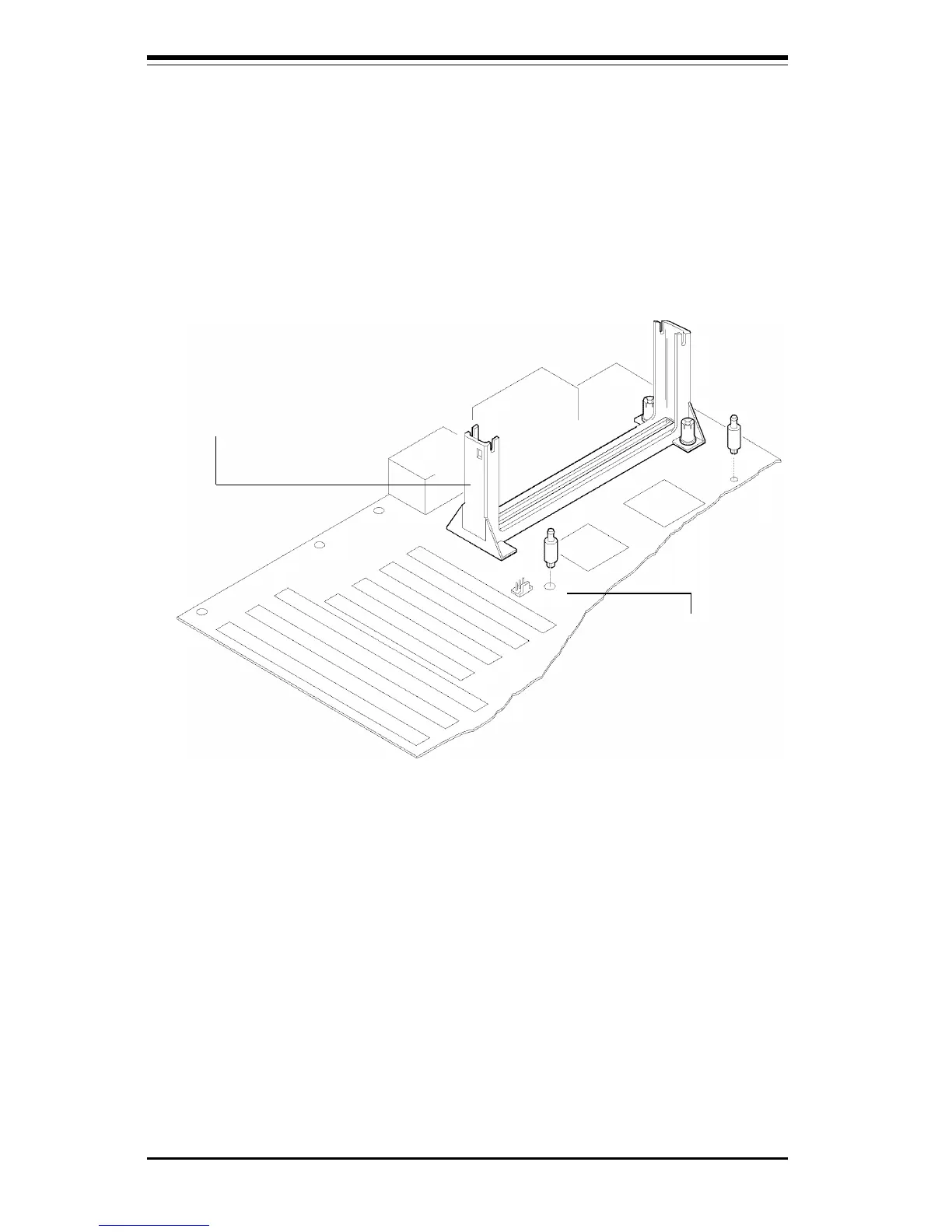
2. Install the retention mechanism attach mount under the motherboard. Do
this before mounting the motherboard in the chassis. Do not screw it in too
tight. Mount the two black plastic pegs onto the motherboard (Figure 2-1).
These pegs will be used to attach the fan/heat sink supports. Note that one
hole and the base of one peg are larger than the other hole and peg base.
Push each peg into its hole firmly until you hear it "click" into place.
Figure 2-1. Mounting the Pegs
Retention
Mechanism
Large peg and hole
3. Slide a black plastic support onto each end of the fan/heat sink making
sure that the hole and clip are on the outside edge of the support. If the
supports are reversed, the holes will not line up with the pegs on the
motherboard. Slide each support toward the center of the processor until
the support is seated in the outside groove in the fan housing.
4. Slide the clip (A) on each support toward the processor, exposing the
hole that will fit over the peg on the motherboard. Push the latches (B) on
the processor toward the center of the processor until they click into place.
5. Hold the processor so that the fan shroud is facing toward the pegs on
the motherboard. Slide the processor (C in Figure 2-2) into the retention
mechanism and slide the supports onto the pegs. Ensure that the pegs on
the motherboard slide into the holes in the heat sink support and that the
 Loading...


