Chapter 2: Installation
2-3
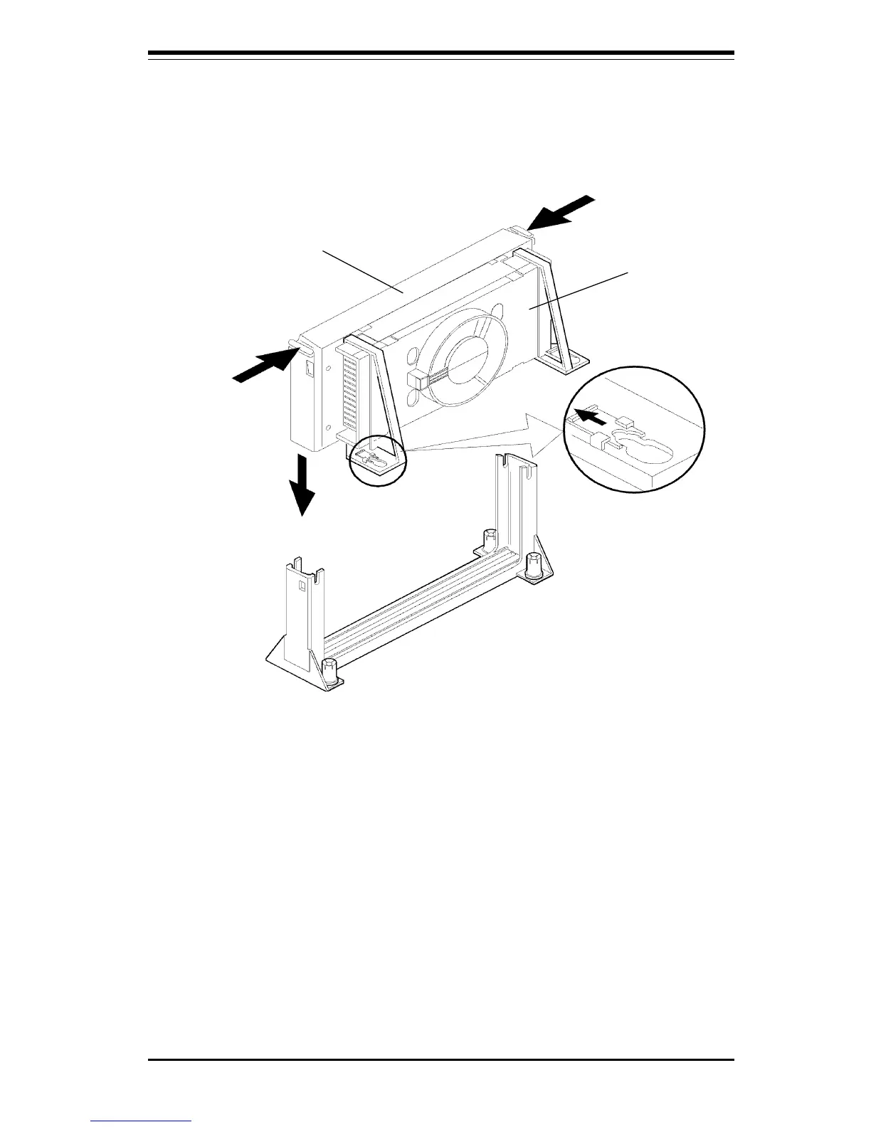
alignment notch in the SECC cartridge fits over the plug in Slot 1. Push the
processor down firmly, with even pressure on both sides of the top, until it
is seated.
Figure 2-2. Retention Mechanism
Top of Processor
B
C
A
Do not screw in too tight!
6. Slide the clips on the supports (A) forward until they click into place to hold
the pegs securely. Apply slight pressure on the peg and push the peg toward
the clip while pushing the clip forward. Push the latches on the processor (B)
outward until they click into place in the retention mechanism. The latches must
be secured for the proper electrical connection of the processor.
Heat Sink
Note: New Pentium III 600E/600EB MHz and faster processors use the
0.18µm process and have a lower CPU core voltage. (“B” is to differenti-
ate 133 MHz front side bus processors from 100 MHz front side bus
processors of the same speed. “E” is to differentiate 0.18-micron from
0.25-micron processors of the same speed.)
 Loading...


