Chapter 5: Advanced Serverboard Setup
5-19
I-SGPIO1/2 & S-SGPIO1 Headers
Three SGPIO (Serial-Link General Pur-
pose Input/Output) headers are located
on the motherboard. I-SGPIO1/2 support
onboard I-SATA 0-5, and S-SGPIO sup-
ports S-SATA 0-3 connections. See the
tables on the right for more information.
Note: NC= No Connection
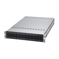
I-SGPIO1/2 & S-SGPIO1 Support
I-SGPIO & S-SGPIO Support
I-SGPIO1 Supports I-SATA0-3
I-SGPIO2 Supports I-SATA4/5
S-SGPIO1 Supports S-SATA0-3
Chassis Intrusion
A Chassis Intrusion header is located at
JL1 on the motherboard. Attach an ap-
propriate cable from the chassis to inform
you of a chassis intrusion when the chassis
is opened.
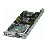
Chassis Intrusion
Pin Defi nitions
Pin# Defi nition
1 Intrusion Input
2 Ground
Power SMB (I
2
C) Connector
Power System Management Bus (I
2
C) Con-
nector (JPI
2
C1) monitors power supply, fan
speeds, and temperatures. See the table on
the right for pin defi nitions.
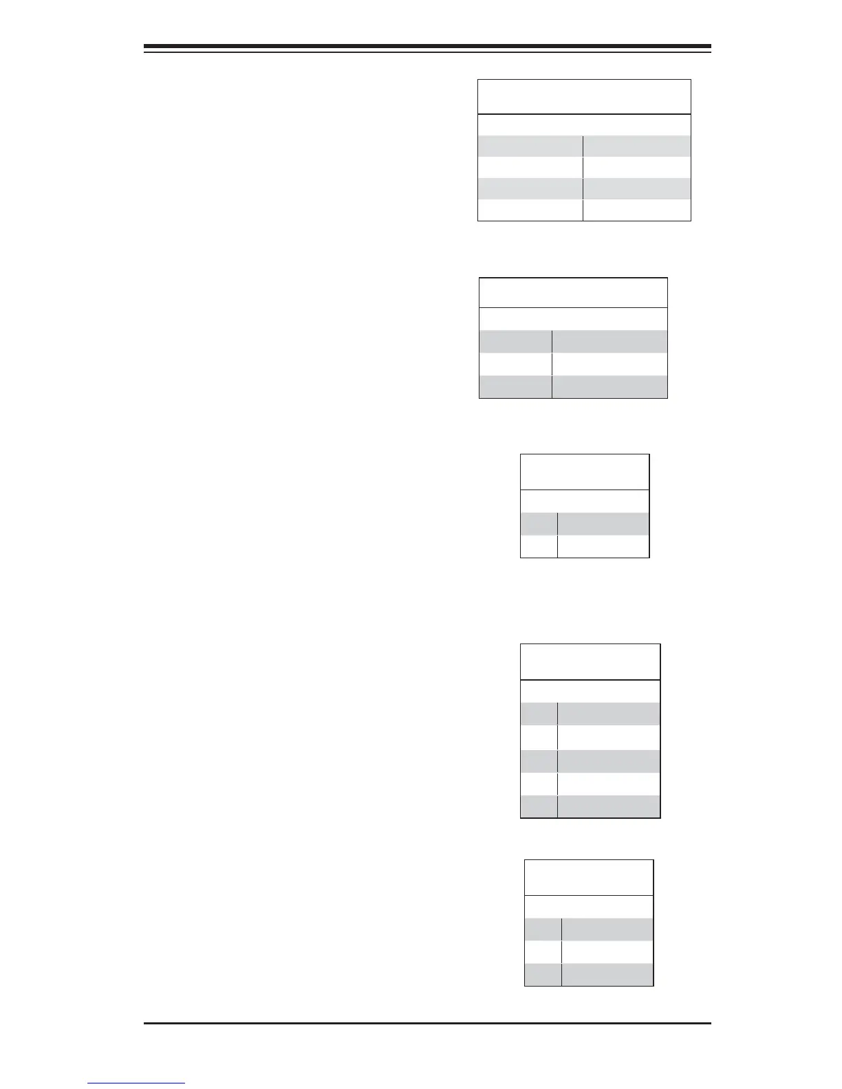
PWR SMB
Pin Defi nitions
Pin# Defi nition
1 Clock
2 Data
3 PMBUS_Alert
4 Ground
5 +3.3V
Standby Power Header
The +5V Standby Power header is located at
JSTBY1 on the motherboard. See the table
on the right for pin defi nitions. (You must also
have a card with a Standby Power connector
and a cable to use this feature.)
Standby PWR
Pin Defi nitions
Pin# Defi nition
1 +5V Standby
2 Ground
3 No Connection
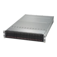
I-SGPIO1/2 & S-SGPIO1 Headers
Pin Defi nitions
Pin # Defi nition Pin # Defi nition
1NC 2NC
3 Ground 4 Data
5 Load 6 Ground
7 Clock 8 NC

 Loading...