5-20
SUPERSERVER 2028R-TXR User's Manual
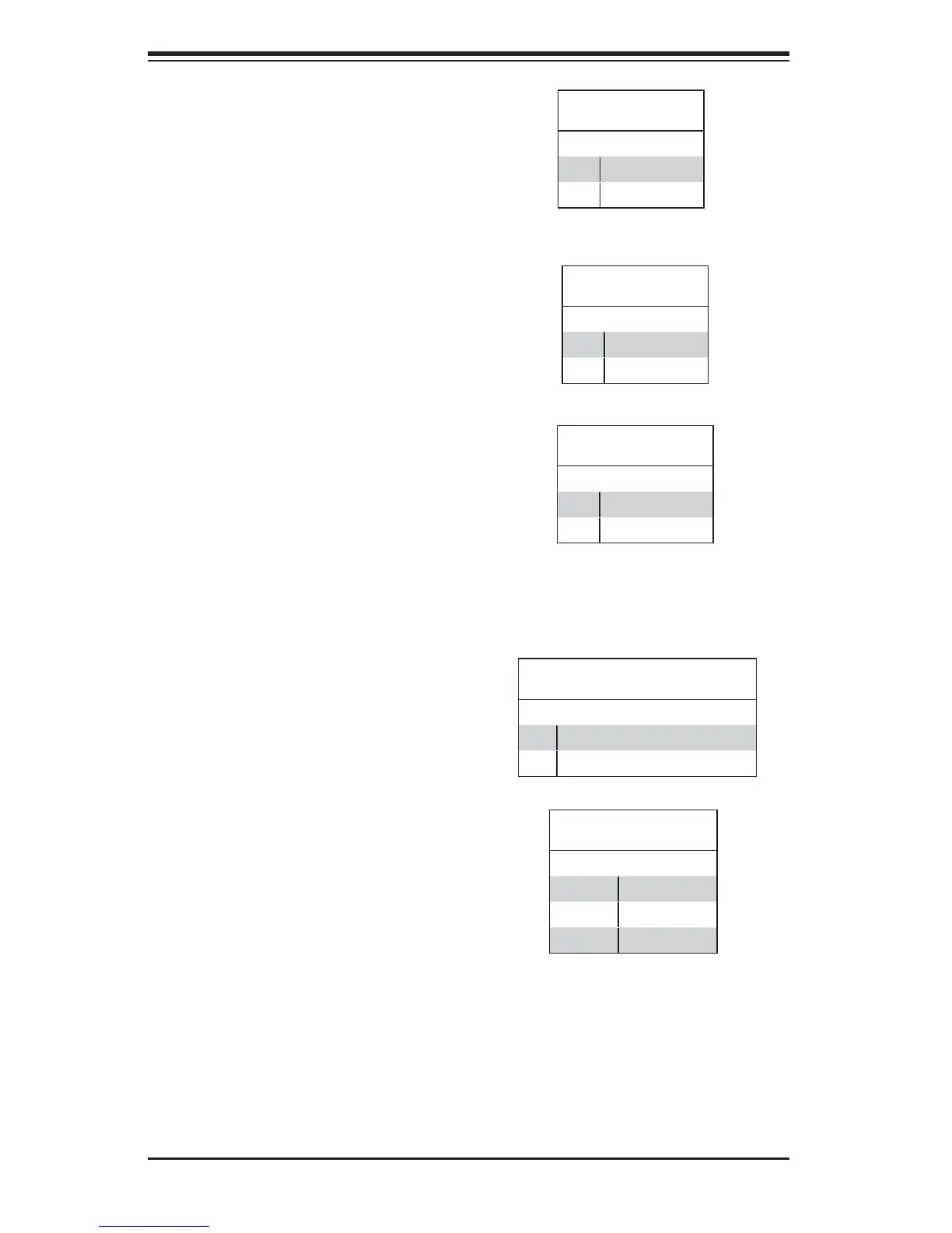
Power LED
The Power LED connection is located
on pins 15 and 16 of JF1. Refer to the
table on the right for pin defi nitions.
NMI Button
The non-maskable interrupt button
header is located on pins 19 and 20
of JF1. Refer to the table on the right
for pin defi nitions.
NMI Button
Pin Defi nitions (JF1)
Pin# Defi nition
19 Control
20 Ground
Power LED
Pin Defi nitions (JF1)
Pin# Defi nition
15 3.3V
16 PWR LED
HDD LED/UID Switch
The HDD LED/UID switch connection
is located on pins 13 and 14 of JF1.
Attach a cable to pin 14 to show HDD
activity status. Attach a cable to pin 13
to use the UID button. See the table
on the right for pin defi nitions.
HDD LED/UID Switch
Pin Defi nitions (JF1)
Pin# Defi nition
13 UID Switch
14 HD Active
Overheat (OH)/Fan Fail/PWR Fail/
UID LED
Connect an LED cable to pins 7 and
8 of JF1 to use the Overheat/Fan
Fail/Power Fail and UID LED connec-
tions. The red LED on pin 8 provides
warnings of system overheating, fan
failure or power failure. The blue LED
on pin 7 works as the front panel UID
LED indicator. Refer to the table on
the right for pin defi nitions.
OH/Fan Fail/ PWR Fail/Blue_UID LED
Pin Defi nitions (JF1)
Pin# Defi nition
7 Blue_UID LED
8 OH/Fan Fail/Power Fail
OH/Fan Fail/PWR Fail
LED Status (Red LED)
State Defi nition
Off Normal
On Overheat
Flashing Fan Fail

 Loading...