Chapter 5: Advanced Serverboard Setup
5-21
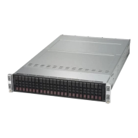
Power Fail LED
The Power Fail LED connection is
located on pins 5 and 6 of JF1. Re-
fer to the table on the right for pin
defi nitions.
PWR Fail LED
Pin Defi nitions (JF1)
Pin# Defi nition
5 3.3V
6 PWR Supply Fail
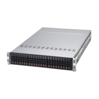
Power Button
The Power Button connection is
located on pins 1 and 2 of JF1. Mo-
mentarily contacting both pins will
power on/off the system. This button
can also be confi gured to function as
a suspend button (with a setting in the
BIOS - see Chapter 7). To turn off the
power when the system is in suspend
mode, press the button for 4 seconds
or longer. Refer to the table on the
right for pin defi nitions.
Power Button
Pin Defi nitions (JF1)
Pin# Defi nition
1 Signal
2 Ground
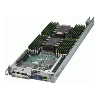
Reset Button
The Reset Button connection is lo-
cated on pins 3 and 4 of JF1. Attach
it to a hardware reset switch on the
computer case. Refer to the table on
the right for pin defi nitions.
Reset Button
Pin Defi nitions (JF1)
Pin# Defi nition
3 Reset
4 Ground
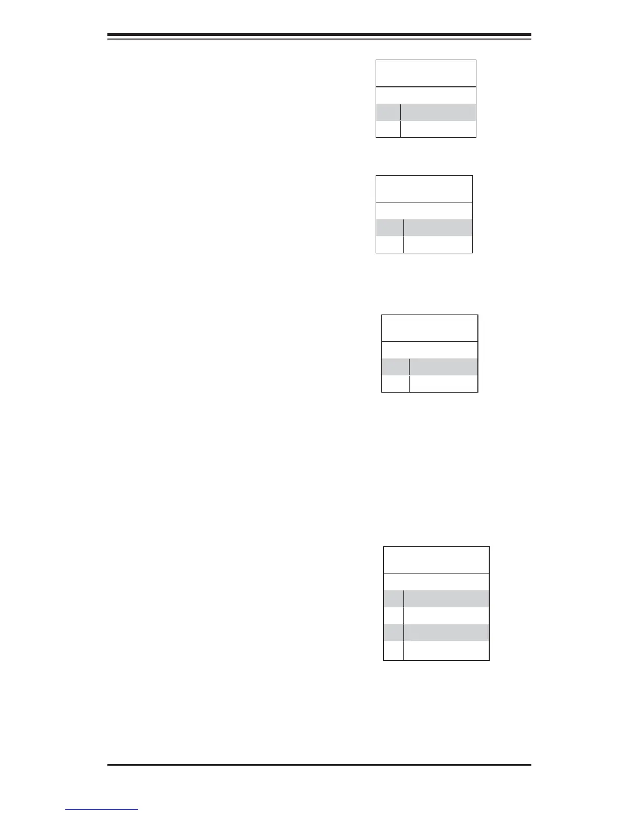
NIC1/NIC2 LED Indicators
The NIC (Network Interface Control-
ler) LED connection for LAN port 1
is located on pins 11 and 12 of JF1,
and for LAN Port 2 is on pins 9 and
10. Attach the NIC LED cables here to
display network activity. Refer to the
table on the right for pin defi nitions.
GLAN1/2 LED
Pin Defi nitions (JF1)
Pin# Defi nition
9 NIC 2 Activity LED
10 NIC 2 Link LED
11 NIC 1 Activity LED
12 NIC 1 Link LED

 Loading...