rev. 08.15.2006.
1-10
1. General Information
Sure Torque recommends that all operators and service personnel scan the Table of Contents to familiarize
themselves with the contents and layout of this technical manual. Since certain modifications have been made or
requested by our customers, this is a general guide and all of the technical information in this manual may not pertain
to your specific machine. Changes in machine design or specifications are a result of continual machine improvement
and Sure Torque reserves the right to change specifications without prior notice.
The following chapter gives a brief description of the operational philosophy of your fully automated ST-LAB, Sure
Torque Electronic Torque Tester System.
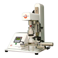
Major components and assemblies are called out on Figure 1-1, ST-LAB Torque Tester General Arrangement,
and referred to in this chapter, and throughout this manual as well. Any optional equipment included with your
machine is listed on the Owners Fact Sheet. Any Changeover specifications are listed on the Machine Tuning Sheet
for the particular closure and container being tested.
Your ST-LAB, “Sure Torque” Electronic Torque Tester, is a fully automated precision instrument designed for a
wide array of container closure test functions. The ST-LAB electronically measures the forces required to apply or
remove threaded screw caps from the containers. Your ST-LAB, with available options, will also apply downward
forces to a childproof closure for the required protocol tests under the Poison Prevention and Packaging Act. The ST-
LAB can also be used for any other test that requires the measurement of an increasing rotary, or linear force to a
peak point, closure container compatibility or failure analysis.
The Sure Torque’s modular design assures minimum maintenance, ease of operation in a minimum of space, and
wide-range of container acceptance capabilities.
ST offers an optional 360° degree test mechanism (refer to section 7.2.1 in this manual) for our ST-LAB unit. This
option measures the largest release torque sensed during a full 360° degree turn of a closure.
1.1. System Overview
The following paragraphs are intended to give an outline of the major components and operational sequences
required to perform the ST-LAB, Sure Torque functions. Major components and assemblies are called out on Figure
1-1, ST-LAB Torque Tester General Arrangement.
The basic ST-LAB Torque Tester System consists of:
1. Control Enclosure.
2. Sturdy mechanical assembly.
3. Integrated pneumatic systems.
4. Electronic components and assemblies required to perform various operational test functions.
The following four sections give a detailed description of each of these assemblies:
1.1.1. Control Interface
The operator’s interface with the Sure Torque unit is controlled through the PLC mounted in the head of the ST-
LAB that regulates the operational cycles, processes the input/output data, and acts as the overall communications
link with the line operator or test engineer. This PLC can easily interface with an on-line or remotely operated host
computer for data collection. Sure Torque will gladly integrate this host computer interface controller PC in your
system.
1.1.2. Mechanical Assembly
The Mechanical System consists of a Base, Chuck and Change Part Components. Please refer to Figure 1-2, ST-
LAB Torque Tester Mechanical Components (Chuck Assembly).