rev. 08.15.2006.
1-13
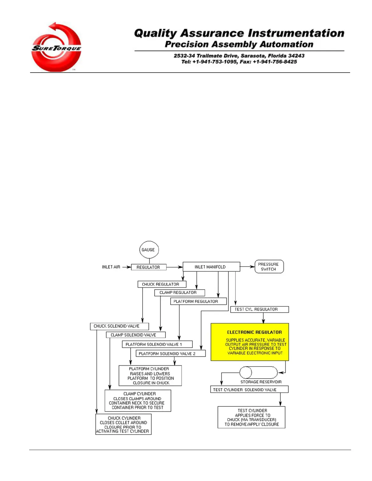
The small Air Storage Reservoir, located between the electronic regulator and the Test Cylinder, provides
smooth, pulse-free and constant pressure airflow to the Test Cylinder, smoothing out the rates of change in the
pressure being fed to the cylinder. This airflow of constantly increasing pressure produces a pulse-free and smoothly
increasing “force” that allows very accurate readings of peak torque values. Clean airflow to the Test Cylinder is
critical for proper operation of this component, and that of the overall machine as well.
Adjusting the “Release/Applied Impulse Time” in the set-up menu regulates the rate of increasing the air
pressure. This number is expressed as 00:00:00 (minutes:seconds:milliseconds) and usually it is in the milliseconds
range. Faster/less accurate or slower/more accurate torque application may be configured with this timer. It directly
controls the rate of the impulses on the PLC output, and this rate is proportional to the torque applied by the chuck.
The rate is programmable in 2 modes. In the first mode the rate is automatically adjusted by the PLC, and this
method is based on special considerations to low torque application (syringes) and high torque applications as well (1
gallon container for chemicals). This mode is optional and does not come with the default configuration. In the other
modes, the operator can change the rate to a static value. The faster the torque application rate is, the worse the
accuracy of the measurement and the shorter the cycle time. A slower rate minimizes the effects of acceleration on
the final torque reading.
It is important to understand that the decreasing this timer will make the torque application faster, while increasing
this timer will make the application slower, because the torque is proportional to the number of the control impulses,
and this timer changes the frequency of these control impulses.
The overall speed/accuracy performance is highly affected by the starting PWM rate as well. This number
controls the zero offset of the torque application. By default we configure the testers with 0 lbfin zero offset, but in
many cases it is adviseable to evaluate the best starting rate for the specific torque application.
Figure 1-3, Standard ST-LAB Torque Tester Pneumatic Diagram.