14
CLUTCH LEVER POSITION SWITCH LEAD WIRE
AND FRONT TURN SIGNAL WIRE HARNESS
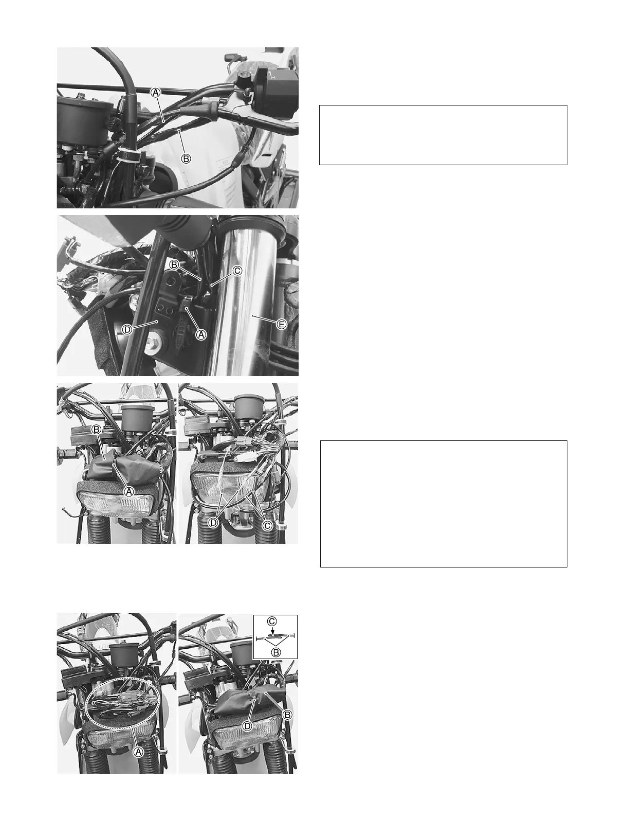
Route the clutch lever position switch lead wire cor-
rectly.
A: Clutch lever position switch lead wire
B: Left switch wiring harness
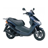
Clamp the clutch lever position switch lead wire and
left switch wiring harness with strap.
A: Strap
B: Clutch lever position switch lead wire
C: Left switch wiring harness
D: Headlight brace
E: Left fork leg
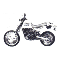
Remove the strap.
Remove the connection cover.
Connect the front turn signal light lead wire coupler
and clutch lever position switch lead wire.
A: Strap
B: Connection cover
C: Front turn signal lead wire
D: Clutch lever position switch lead wire
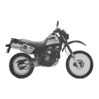
Arrange the wiring harness.
Cover the connections with connection cover.
Lock the velcro fastening.
Clamp the connection cover with strap.
A: Connection
B: Connection cover
C: Velcro fastening
D: Strap
NOTE:
The routing of clutch lever position switch lead wire
is the same as that of handlebar left switch wiring
harness.
NOTE:
• Connect the black coupler of left turn signal light
lead wire to the gray coupler of the main wire har-
ness.
• Connect the black coupler of right turn signal light
lead wire to the black coupler of the main wire
harness.
• The clutch lever position switch lead wire match
colors (yellow and green tracer) and connected.