AMI Codes-II
Product Description
A-96.250.571 / 050517 11
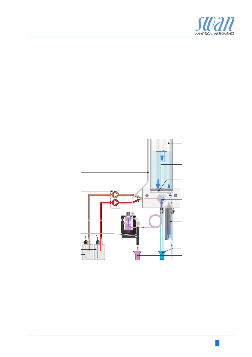
Fluidics The sample flows through the sample inlet [F] and the filter vessel
[G] into the constant head [A]. Adjust the flow regulating valve [D]
so that always a small part of the sample flows through the overflow
tube [B] into the drain [H]. A part of the sample flows through the
photometer inlet [C] into the mixing chamber [E], where the re-
agents [J] and [K] are added by the peristaltic pump [O] and mixed
with the sample. The mixed sample flows through the photometer
[N] and disinfectant is measured. If KI and Buffer are mixed in the
reagent canister [K] monochloramine is measured.
After the measurement the sample flows through the outlet of the
photometer where it will be aerated through air inlet [P] to generate
bubbles. Then the sample flows through the bubble detector [M]
into the photometer drain [I].
A
B
C
D
E
F
G
H
Constant head
Overflow tube
Photometer inlet
Flow regulating valve
Mixing chamber
Sample inlet
Inlet Filter
Constant head drain
I
J
K
L
M
N
O
P
Photometer drain
Reagent Oxycon on-line DPD
Reagent Oxycon on-line Buffer
Reagent level detector
Air bubble detector
Photometer
Peristaltic pump
Photometer air inlet