22 A-96.250.761 / 161017
AMI INSPECTOR pH
Installation
3.6.3 Relay 1 and 2
NOTICE: For resistive loads only; do not use with capacitive or
inductive loads. Max. load 100 mA/50 VAC.
For programming see Menu Installation 5.3.2/3, p. 61.
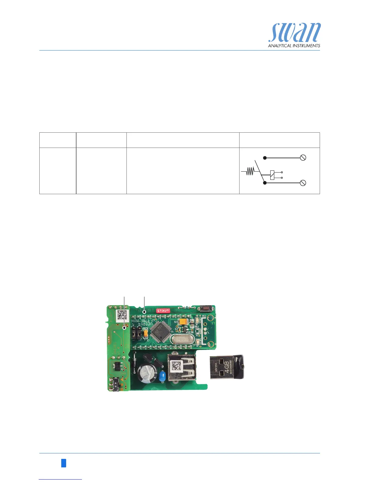
3.7. Signal Output
The signal output 0/4–20 mA PCB is plugged onto the USB inter-
face PCB.
NOTICE: Max. burden 510 Ω.
Terminals 16 (+) and 15 (-).
For programming see menu 5.2 Signal Outputs, p. 55.
.
Terminals Description
Relay connection
NO
Normally
Open
6/7: Relay 1
8/9: Relay 2
Inactive (opened) during normal
operation and loss of power.
Active (closed) when a pro-
grammed function is executed.
A
B
Signal output 0/4–20 mA PCB
USB interface