Do you have a question about the Swann AMI Oxytrace and is the answer not in the manual?
Explains the purpose and importance of safety instructions for instrument operation.
Defines safety symbols for DANGER, WARNING, and CAUTION notices.
Identifies required safety gear such as safety goggles and gloves.
Lists common hazard symbols and explains their meanings.
Covers user responsibility, legal requirements, and safe operation rules.
Explains the instrument's application, Clark principle, and temperature compensation.
Details the QED-specific feature for verifying system operation and response.
Describes the programmable analog outputs for measured values.
Explains programmable potential-free contacts for limits or timers.
Details the function and operation of the dedicated alarm relay.
Describes the function and purpose of the instrument's input terminal.
Lists safety aspects including non-volatile memory and over-voltage protection.
Lists optional interfaces like USB, RS485, and HART.
Illustrates the sample flow path for the AMI Oxytrace.
Illustrates the sample flow path for the AMI Oxytrace QED.
Lists specifications for power, housing, requirements, accuracy, and range.
Shows physical dimensions and mounting hole layout of the panel.
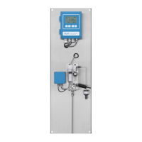
Labels the main components of the AMI Oxytrace instrument.
Labels the main components of the AMI Oxytrace QED instrument.
Details the transmitter's dimensions, specifications, and electrical connectors.
Lists technical data, measuring range, accuracy, and material for the sensor.
Details specifications and dimensions of the QV-Flow PMMA OTG flow cell.
Details specifications for the B-Flow SS316L OTG flow cell.
Specifies conditions and limitations for instrument installation and use.
Outlines requirements and checks before instrument installation.
Provides guidance on mounting the instrument panel vertically.
Details procedures for connecting sample and waste lines.
Describes the process for connecting stainless steel tubes using Swagelok fittings.
Describes connecting the FEP tube to the waste funnel.
Steps for installing the oxygen sensor into the flow cell.
Covers wiring requirements, safety warnings, and cable gland usage.
Shows the wiring schematic for the AMI Oxytrace transmitter.
Shows the wiring schematic for the AMI Oxytrace QED transmitter.
Details the power supply connector, requirements, and fuse types.
Details the function and connection of the alarm relay.
Explains the configuration and operation of relays 1 and 2.
Describes the programmable current outputs for measured values.
Describes the additional third signal output option.
Details connection and configuration for Profibus and Modbus interfaces.
Explains the HART interface for communication.
Describes the USB interface for data logging and firmware updates.
Steps to establish and adjust the sample flow rate.
Guides on programming instrument parameters and external devices.
Explains the function of each key on the instrument panel.
Describes the instrument display elements and status symbols.
Outlines the menu hierarchy and access levels of the instrument software.
Provides instructions on how to modify instrument settings and values.
Provides a schedule of recommended maintenance tasks based on frequency.
Instructions on safely shutting down the instrument before maintenance.
Details procedures for cleaning and maintaining the oxygen sensor.
Step-by-step guide for replacing the sensor's electrolyte.
Instructions for cleaning the sensor and the flow cell.
Procedure for cleaning and maintaining the Faraday electrode.
Step-by-step guide for calibrating the oxygen sensor.
Procedure for verifying the sensor's zero point using a sodium sulfite solution.
Explains how to perform manual and automatic Faraday verification.
Explains the instrument's QA functions, levels, and procedures.
How to enable the quality assurance procedure on the instrument.
Describes pre-test checks required before performing QA procedures.
Instructions for connecting sample lines for comparison measurements.
Detailed steps for performing comparison measurements in QA.
Steps to properly complete the QA measurement process.
Procedure for replacing blown fuses in the instrument.
Instructions for preparing the instrument for extended periods of non-operation.
Describes the Messages menu for errors and maintenance tasks.
Explains the Diagnostics menu for viewing instrument data.
Describes the Maintenance menu for calibration and settings.
Explains the Operation menu for user-adjustable parameters.
Describes the Installation menu for system configuration.
Lists active errors and their status.
Lists necessary maintenance tasks and their status.
Shows the instrument's error history.
Reviews diagnostic values from the last sensor calibrations.
Provides information on case temperature and air pressure.
Reviews quality assurance values and check statuses.
Shows sample identification and related parameters.
Displays the current status of all inputs and outputs.
Shows programmed communication settings for installed interfaces.
Lists reagents used and provides links to download MSDS.