8
For the robot to be able to send these signals to the Scan S25, +24V must be supplied to +24V_ROB pin 1 and
GND to GND_ROB pin 13.
The status of the robot needs to be provided to the Scan by the double signal ROBOT_OK1 pin 4 and ROBOT_OK2
pin 5, a binary 1 state indicates that the robot is ready and a binary 0 state that the robot is faulty.
The status of the Scan S25 is provided to the robot by a double signal SCAN_OK1 pin 2 and SCAN_OK2 pin 3, a
binary 1 state indicates that a Scan S25 is ready and a binary 0 state that a Scan S25 is faulty.
If the binary state is different on the two inputs, e.g. ROBOT_OK1 at 1 and ROBOT_OK2 at 0, the Scan considers
the robot state as faulty.
If one of the two elements is in fault condition (Emergency Stop Button or robot), the following two actions must
be carried out (in this order) to make the Scan S25 ready again :
1. Check the safety components and restore them to their normal operating state (restore the safety signals).
2. Start a measurement, from the Scan S25, ReflexScan or the robot, or restart the Scan from the robot RES-
TART_ROB pin 7 (signal of at least 200 ms).
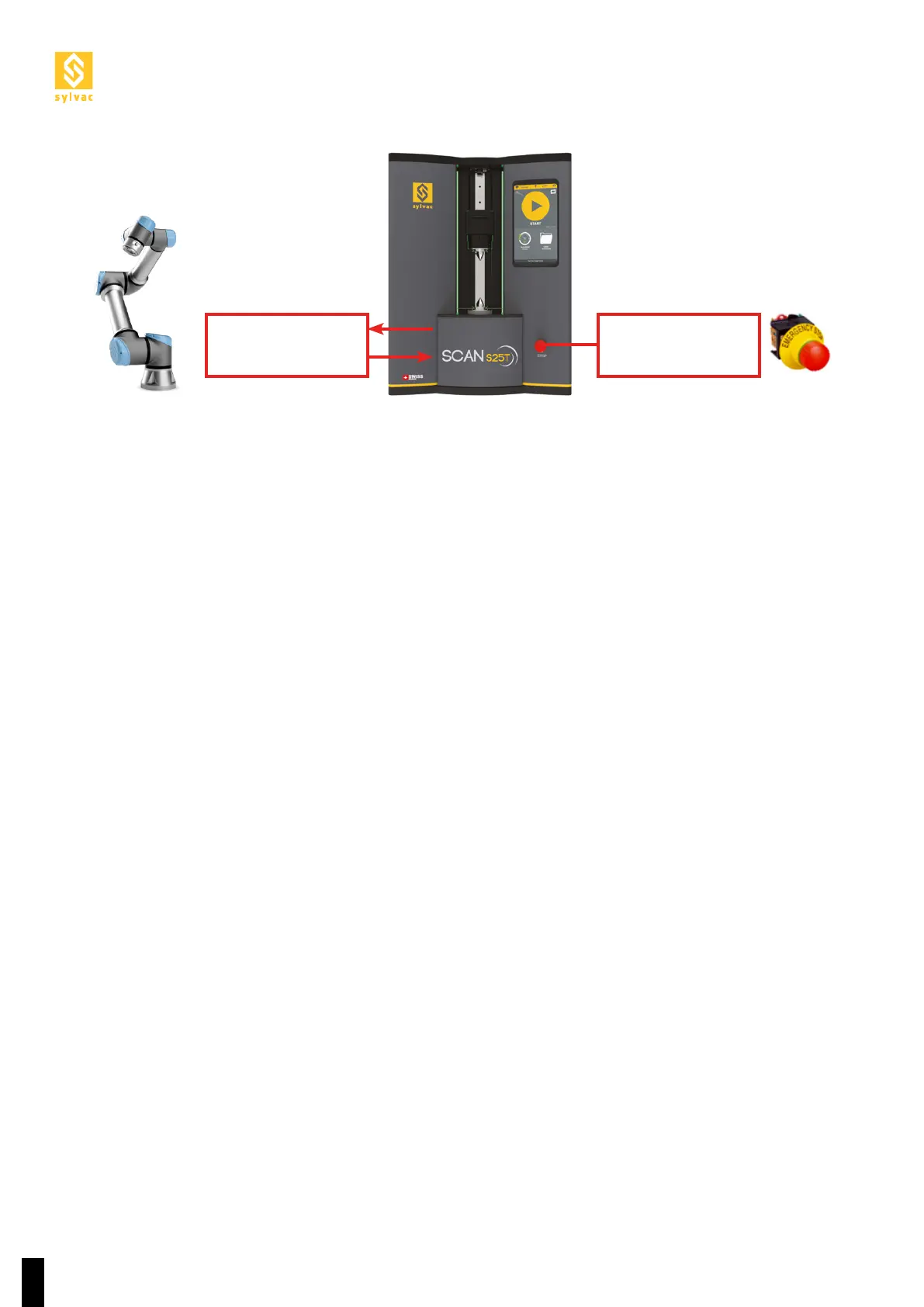
For the Scan and the robot to work together, the diagram in the next Section 2.6 must be observed.
Emergency Stop
Button
Robot Emergency
Stop