16
Loaded Program 1
3-bit code (0 to 7) of the currently selected program.
Loaded Program 2
Results
Result Ready
“True” state when the program has finished its execution and the
results are ready.
No Result “True” state when the program has not returned any results.
Pass
“True” state when all measurement results are within the
tolerances defined by the loaded program.
Failed
“True” state when all measurement results are not within the
tolerances defined by the loaded program.
Warning
“True” state when one of the dimensions needs to be corrected
in the program.
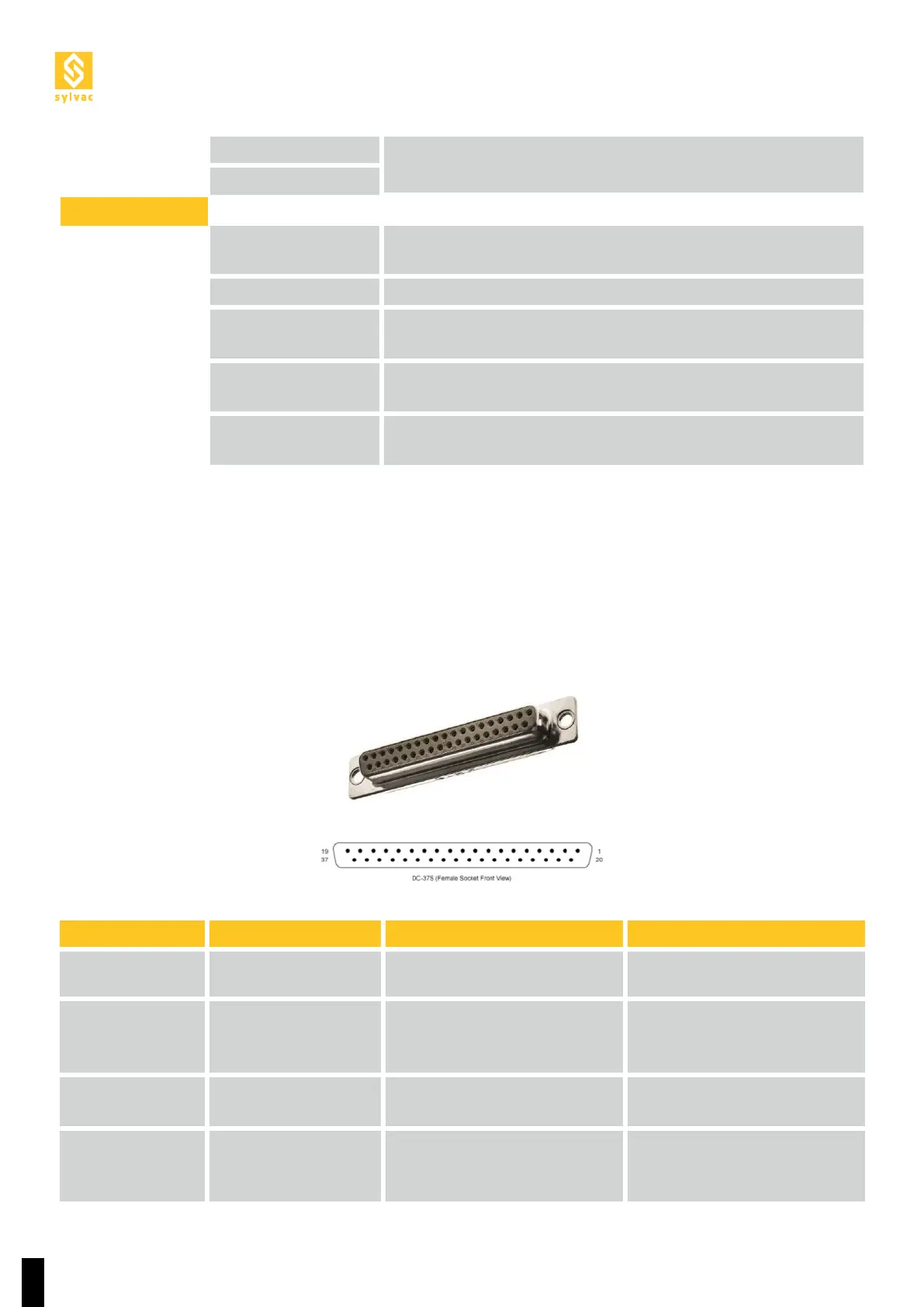
Pin
I/O SCAN
Function Type of signal
1
+24V (Robot)
+24V from the robot (common
with the other connectors)
2 GND (Robot)
Ground from the robot
(common with the other
connectors)
3
+24V (Scan)
+24V from the Scan (common
with the other connectors)
4
GND (Scan)
Ground from the Scan
(common with the other
connectors)
* Optional, you must install a pneumatic chuck to use these signals.
**Warning! A part that is not held properly before this signal is sent may fall and cause damage or injuries.
All inputs and outputs, to and from the Scan, must be +24V (binary 1), or GND (binary 0). All signals to the
Scan must come from the robot.
5.4 Description of the main D-SUB 37p I/O pins