18
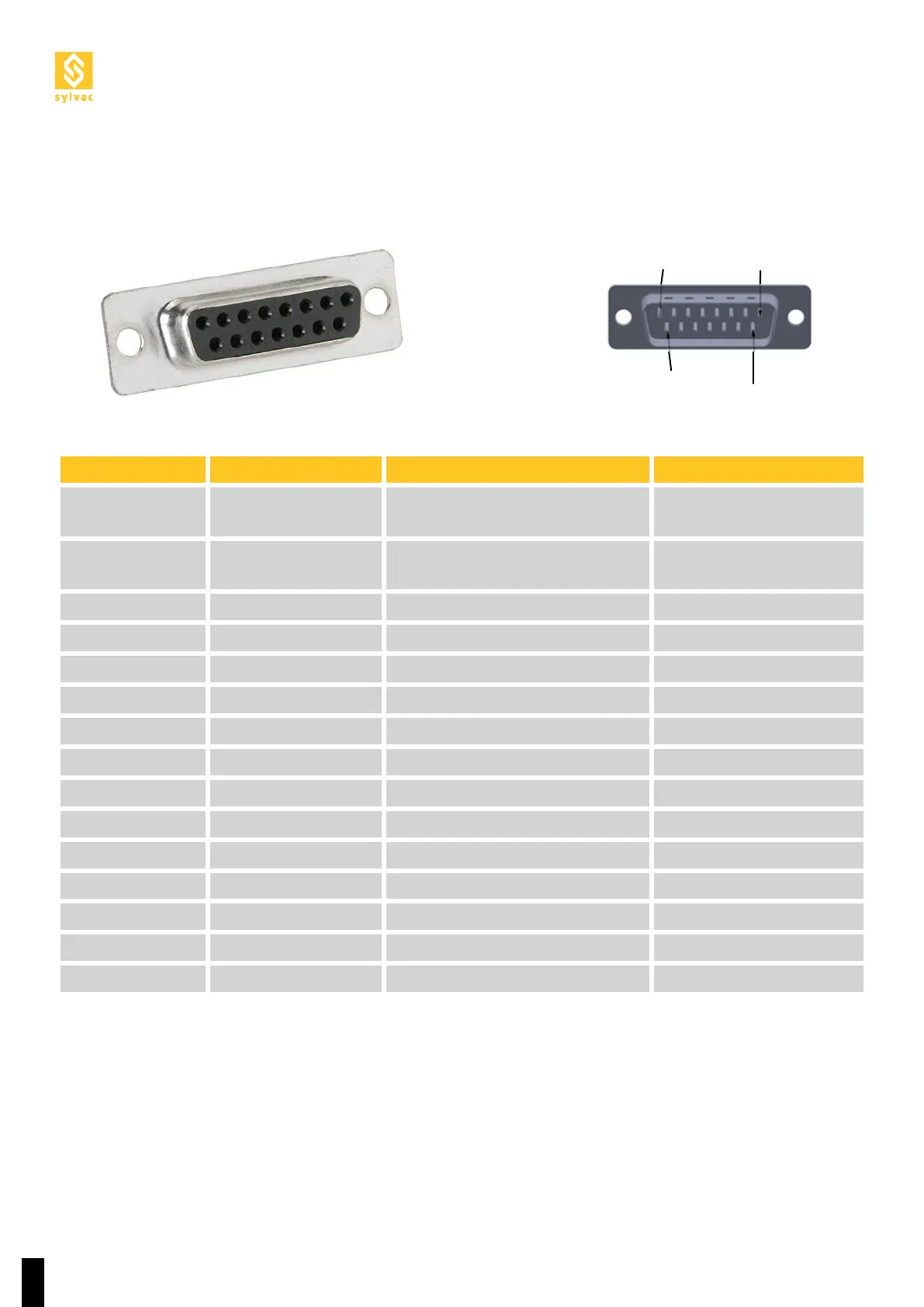
PIN #8
PIN #15 PIN #9
FEMALE
PIN #1
All inputs and outputs, to and from the Scan, must either be at +24V (edge 1) or at GND (edge 0). All signals
to the Scan must come from the robot.
«This connector is reserved for future use requiring more I/Os.»
5.5 Description of pin D-SUB 15p I/O additional tools
PIN I/O SCAN Function Type of signal
1 +24V (Robot)
+24V from the robot (common
with the other connectors)
2 GND (Robot)
Ground from the robot (common
with the other connectors)
3 IN17
4 IN18
5 IN19
6 IN20
7 IN21
8 IN22
9 OUT17 Chuck Open (SW) Persistent
10 OUT18 Chuck Closed (SW) Persistent
11 OUT19
12 OUT20
13 OUT21
14 OUT22
15 Earth Shielding