5120A/5115A Operations and Maintenance Manual 5
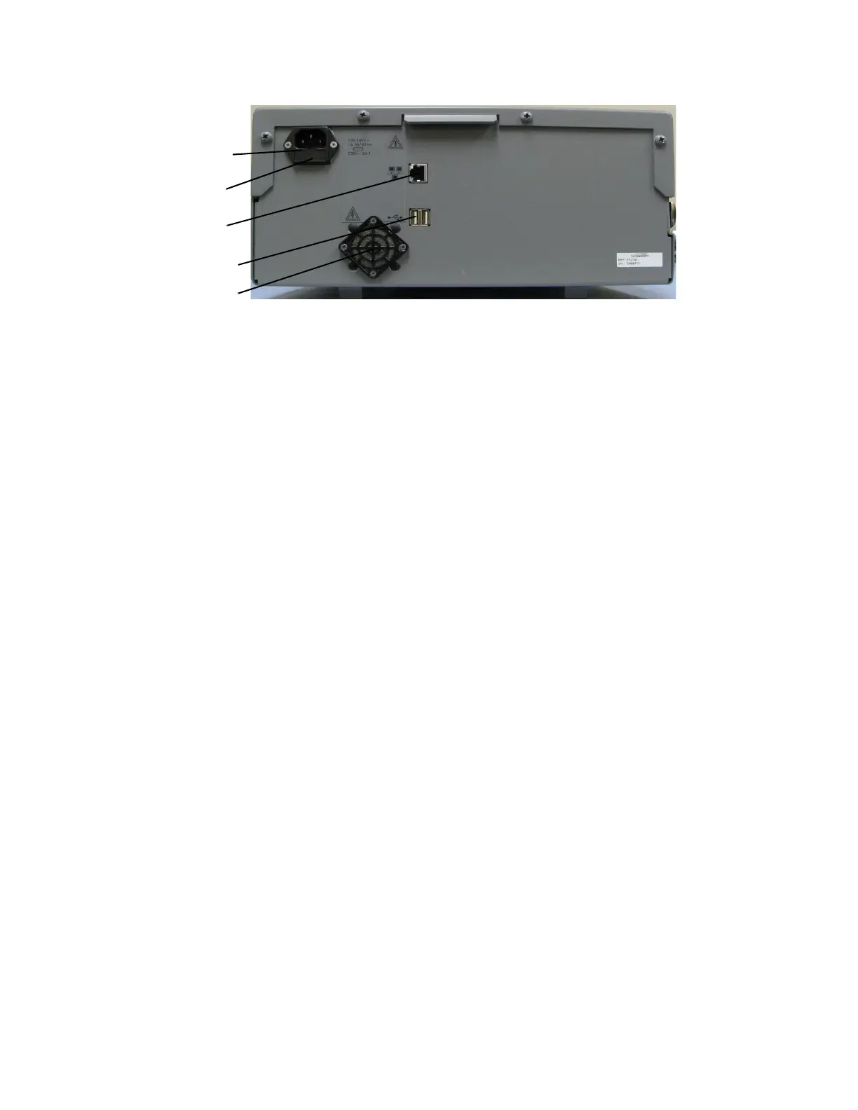
Figure 2: Rear Panel
All measurements are made between the Input and Reference ports. To ensure that measured
characteristics are those of the Input signal, a clean and stable signal must be supplied to the
Reference port of the PNTS. The 5120A-01 is equipped with two internal oscillators that can serve
this function, to use internal reference signal, simply do not attach a a signal to the reference port.
Consult “Appendix A, Electrical Specifications” on page 82 for internal oscillator performance
specifications.
The phase noise and phase spurs that are present on the Reference port are scaled by a factor of
20*log (Finput/Fref) when displayed. Consider the following example: A spur on a 10 MHz signal
is connected to the Input port with a clean 5 MHz connected to the Reference port. The spur
reading is -50 dBc. If the signal cables are swapped between the ports, the spur reading will be -56
dBc.
Power
connection
Ethernet
port
USB ports
Fuse
Cooling Fan
Filter
 Loading...