Description
Specifications
24 X72 Desiger’s Reference and User’s Guide 097-10603-01 Rev. A – November 2004
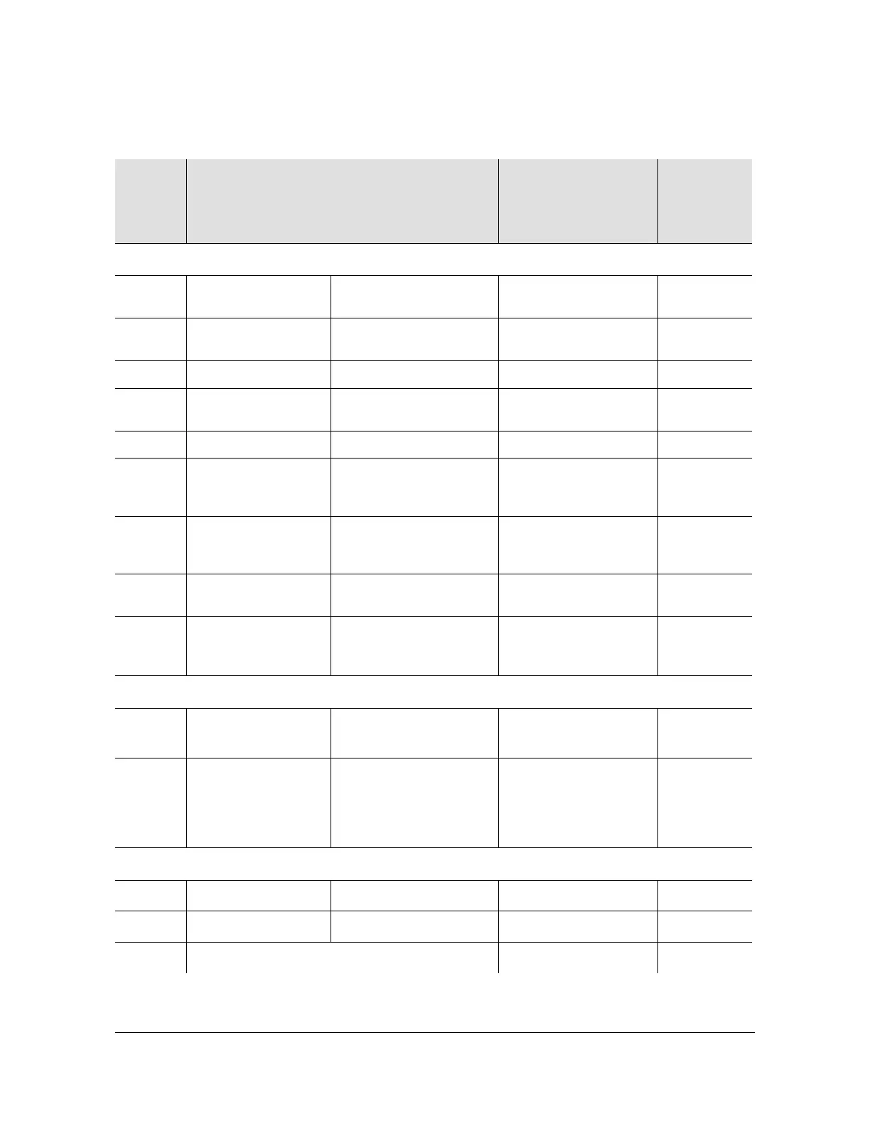
Table 1-3. X72 Design Operating Characteristics
Symbol
Characteristic
(Unit in ambient still air – convection)
– 40° C to 85° C
Base-plate
Min Typ
Max
Units
Digital Inputs/Outputs
V
CC
Supply relative to
ground
10 to 32 volt unit 10 32 V
V
IH
High level input
voltage
DIN 2.5 5.5 V
1PPSIN 1.8 5.5
V
IL
Low level input
voltage
DIN 0 0.8 V
1PPSIN 0 0.8
V
OH
High level output
voltage
DOUT, Service, Lock
@IOH = –0.33mA @
IOH = 0 mA
3.3 V
FXO, FACMOS,
1PPSOUT @IOH =
–3.5mA
3.5
V
OL
Low level output
voltage
DOUT, Service, Lock
@IOL = 0.1 mA
0.4 V
FXO, FACMOS,
1PPSOUT @IOL =
1.7 ma
0.4
Analog Inputs/Outputs
V
FC
Frequency control
input voltage range
Range of ±1.5xE
–9
with
resolution of 2.0xE
–12
5V
P
SO
FSINE output power
range
Factory set with 7.0
(Output load of 390pF
cap & 50 Ω resistor
within 4 inches of
FSINE pin).
5.0 min.
8.0 max.
6.5 typ.
dBm
Frequency Control
∆F/F
R
Control Range Analog (freq ctrl pin)
–1.5xE
–9
+ 1.5
∆Hz/Hz
Digital Interface
–1.0xE
–6
–1.0xE
–6
∆F/F
RES
Frequency Control Resolution 2.04
E
–12
∆Hz/Hz
 Loading...