Design Integration Considerations
Mechanical Considerations
28 X72 Desiger’s Reference and User’s Guide 097-10603-01 Rev. A – November 2004
Mechanical Considerations
Mounting Recommendations
To mount the X72 to a circuit card or chassis, use the four mounting holes located at
the corners of its base plate. An interface cable or adapter card is required to
access the X72 outputs and to interface with a host system.
Use four M3 stainless steel screws with a minimum penetration depth of 0.2 inch
(5.08 mm) and a maximum of 0.5 inch (12.7 mm) to mount the unit.
Recommended Mating Connectors
Shielded cable must be used between the X72 connector and the host system
connector to meet noise and emissions requirements noted in the X72 engineering
specifications. It is recommend that for typical applications this interface cable be no
longer than 4 inches (10 cm).
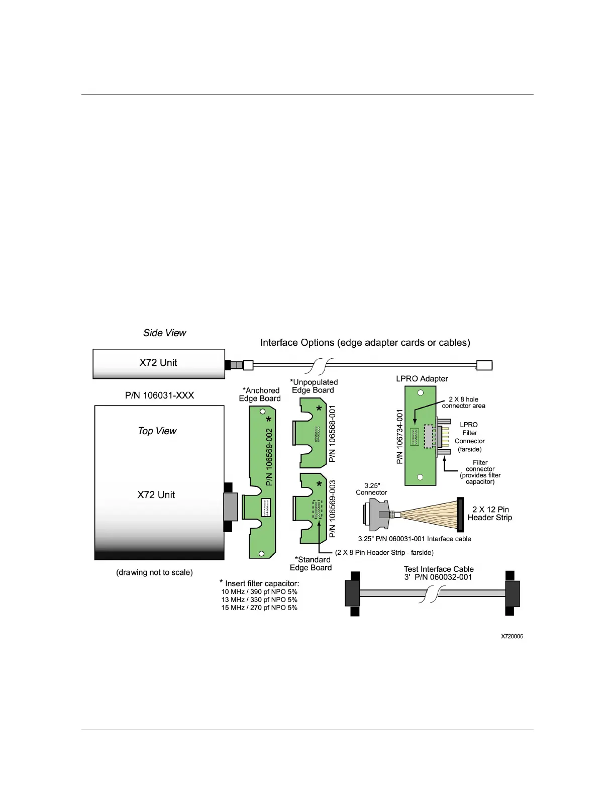
Figure 2-1 Adapter Cards, Cables, and Options
 Loading...